Introduction: Wooden Farm Toys for Haymaking
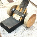
I made these for my son when he was a boy. They are made from 3/4 inch birch. They would make a good Christmas gift for a young male in your family.
Step 1: The Tractor
The degree of detail is not for an exact replica, but suitable to stir the imagination of a young boy. Rather than give measurements I included a scale in inches in most of the photos. Begin by drawing the profile of the tractor body. The wheels were turned on my lathe. Axles are from 3/16 inch steel rod with end cap retainers from the hardware store. The exhaust stack is a piece of 1/4 inch welding rod for an oxy-acetylene torch. The steering wheel assembly is from a 3/8 inch carriage bolt with the square portion under the head ground away to make the column round. There will be more on the seat and the gear shift later.
Step 2: Rear of the Tractor
In addition to the piece for the tractor frame, the other key piece (in addition to the wheels) is the axle member. I cut a notch in the underside of the tractor frame and in the upper side of the axle member to make a tight fitting lap joint. The red lines define the notch cut into the axle member. I drilled a 3/16 inch hole across the axle member that also goes through part of the tractor frame. When the 3/16 inch axle rod is inserted (yellow line), the tractor's main pieces are locked together.
Step 3: Front of the Tractor
The front wheel assembly is in the fashion of a row crop tractor with each wheel canted inward slightly at the bottom. The wheel assembly is from a steel rod 5/16 inch in diameter with a 3/16 inch rod welded across its end to make an inverted "T". I bent the 3/16 inch rod ends downward a little to achieve the canted effect.
Step 4: The Front Turns But Does Not Come Out
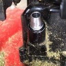
The front wheel assembly can be turned to make the tractor follow a curved path. Notice the yellow arrow. It points to a nail that keeps the wheel assembly from coming out. Notice the red lines. They give an approximation of how I ground an indentation around the vertical part of the wheel assembly so the nail keeps the front wheels from falling out of the bottom of the tractor.
Step 5: The Seat and Gear Shift
I made the seat to attach with some glue and a wood screw. I drilled into a square block with a spade bit and then opened one side by hand with a chisel. The seat is sized to accomodate a Fisher-Price "Little People" person. The gear shift is a piece of 1/8 inch rod bent to look like a shift lever. I drilled a hole to mount it, making it at an angle so it would appear the shift lever is actually in a gear.
Step 6: The Drawbar Hitch
The drawbar hitch is a piece of 1/8 inch strap iron. I held the drill by hand and the holes skated a little so that I had to mount the steel crooked to center the hole. Notice the metal washers between the wheels and the axle's cross member.
Step 7: The Baler
The baler is made from pieces of 3/4 inch birch glued together to make 1 1/2 inches in thickness. The mouth of the baler is made from the lower piece that protrudes a bit and has a rounded nose. The opening is made from rabbeting away part of the top piece. The drawbar is from some 5/16 inch aluminum rod. I bent it so the baler tracks offset to the side. When baling hay, the tractor never drives on the hay, but usually to one side of it. (Some new balers require the tractor to straddle the hay winnow.) The fender washers suggest a flywheel, which is very common to a baler.
Step 8: Side of the Baler
This gives a view of the side of the baler. A faux wooden bale is in the chute. Notice also the drawbar on the rear of the baler for pulling the wagon onto which the bales are loaded by someone on the wagon.
Step 9: The Other Side of the Baler
There is not much critical detail on this side of the baler.
Step 10: Bottom Details
You can see how I inletted for the wagon drawbar hitch. This allowed me to use only one screw. The wheel axle is held in place with several staples. Birch is fairly hard wood and the staples do not back out easily. The red rectangles represent dowel pins to attache the two sections of the baler and hold them together. In addition to dowels, the two pieces are also glued. (The front of the baler is toward the bottom of the photo.)
Step 11: Rear of the Baler
This gives a good detail image of the bale chute. The faux bale has been removed. Note how the front drawbar angles off to the left.
Step 12: Pin the Drawbar for Rigidity
The red arrow indicates a pin that goes into a hole in the drawbar so it cannot twist or come out. The yellow arrow gives a good view of the rounding on the bottom portion of the baler's mouth. You can also see the fender washer flywheel clearly.
Step 13: The Hitch in Detail
The drawbar needs a hitch to attach to the tractor's drawbar hitch. I attached a flat piece of steel to the underside of the aluminum rod. Notice the right end in the photo. I ground it down to make a round pin and then bent the pin upward so it can fit into a recessed hole in the round rod. The red lines indicate the portion hidden inside the hole. A screw attaches the flat piece to the round rod, but I damaged the threads with a cold chisel so the nut cannot turn or loosen. See the azure blue arrow.
Step 14: Attaching the Baler or Wagon to the Tractor
The hitch design is very much like you would find on a real tractor, baler, and wagon. I used a special small double-headed nail for the hitch pin. The wagon is attached to the tractor in this photo.
Step 15: The Wagon
This is a side view of a flat bed bale wagon. It does have a removable upright back section.
Step 16: The Back Underside
I glued three pieces of birch together and used a rotary planer on my radial arm saw to make the outer portions thinner than the center. You can see the staples I used to hold the removable upright wagon back in place. The rear wheel carriage is glued to the underside of the wagon. Note the steel washers between the wheels and the carriage.
Step 17: Back of the Wagon
This gives more complete view of the removable wagon back. Initially I glued the cross member to the uprights, but it is one piece and it curved with changes in humidity over the years. The glue broke away and I added some #4 sheet metal screws recently.
Step 18: Front Undercarriage
The front undercarriage for the wheels is self-explanatory. There is a steel washer above the screw that allows the undercarriage to turn for going around a corner.
Step 19: The Bales
The bales are from scraps of birch. Round both ends of a section cut to a suitable length. Then slice the bales off from one another. Sand to make them smooth. Finish this project according to your tastes.
Even though I made this more than thirty years ago, some young boys played with it this week and it still held as much magic as it had when it was first made.


