

Introduction: 3D Printed Wall Clock With Kinetic Art and LEDs


3D Printed Wall Clock with Kinetic Sculpture and LEDs
Hello everyone! I am back with an awesome 3D printed wall clock. It has kinetic sculpture located at the center and hour balls light up with a toggle switch. Each ball has an LED inside !!! It is one of my really good prints. I build this entire project in a weekend. I hope you guys enjoy it. I designed this clock from scratch and used Autodesk inventor professional 2020 for the design.
I also prepared a 30 min long video for you to watch how to build this clock step by step. Don't forget to check it out!
Let's move to the steps to build this awesome clock!

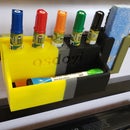
Step 1: Tools and Parts List

Which parts do you need to build this clock? Here is your part list:
- Colorful LEDs x16 (3V each)
- A cheap clock (we will take the interior core)
- Superglue
- Hot glue gun
- Soldering machine
- thin cables
- Solder
- on/off toggle switch
- power supply 3~3.5V
- 3D printer & filaments (colors are up to you!)
- 3D pen
- Electric tape
- Tweezers
- Pliers
- Cutters
- Duck tape or alike
In addition to the part list above you need to 3D print my designs which you can see in the next step!
Step 2: 3D Printing Settings and Stl Files to Print


I attached all the stl files you need to this step. Let summarize what we have and how many of each we need to print. In total, you need to 3D print 41 pieces!!!
- arm.stl x12
- clock ball door x12
- center2.stl x1
- clock ball 1.stl x1
- clock ball 2.stl x1
- clock ball 3.stl x1
- clock ball 4.stl x1
- clock ball 5.stl x1
- clock ball 6.stl x1
- clock ball 7.stl x1
- clock ball 8.stl x1
- clock ball 9.stl x1
- clock ball 10.stl x1
- clock ball 11.stl x1
- clock ball 12.stl x1
- Kinetic half 1.stl x1
- Kinetic half 2.stl x1
- short arm.stl x1
- long arm.stl x1
You can see the 3D CAD model at this step for the assembly of the clock to help you visualize.
What are the important print settings you should use during the print? Down below you can see the print settings that I think the most important:
- Layer height: 0.1 mm
- wall thickness: 0.8 mm
- infill: 20 %
- print temp: 200 C
- print speed :60 mm/s
- Retraction: 6.5 mm
- Brim: 3 mm (for kinetic sculpture use 1 mm)
You can see the rest of the setting in the Cura setting figure attached to this step.
Attachments


Step 3: Preparing the Hour Ball Numbers


At this step having a 3D pen makes things simpler and faster. What we need to do is to fill the number gaps with black PLA filament. You can also 3D print these numbers and sand them to fit in. (Font of the numbers is Arial and the size is 25)
Another approach is to fill these gaps with hot glue gun silicone and then paint them with a permanent black marker. I used this method as well and it worked well. Can you tell the difference? Clock ball #1 is done with this method while the rest was done with 3D pen usage.
Step 4: Preparing the Clock Core / Center


First, you need to buy a clock. I purchased this one from Fred Meyer for 10$, to be honest. Also if you prefer continuous second arm movement in the clock it will be better for the kinetic motion of the center part.
First, open the clock into two half. Then remove the arms of the clock on the front face (by pulling up). Later turn the clock upside down and remove the clock core by squeezing the holders at the back. Finally, you will be able to remove the core of the clock. (see the video)
After you remove the pieces, get the 3D printed center part, and attach the clock core into our 3D printed piece from the back section. Use a hot glue gun and drop 4 droplets to glue the core into the3D printed piece. The white shaft of the clock core should be at the center of our hole at the surface of the printed piece.
Step 5: Attaching Kinetic Art Piece and Arms


For this step be careful to not glue your fingers, since we have tiny features. Glue the ring of the kinetic sculpture on top of our centerpiece and make sure they are aligned. Later, glue our kinetic sculpture half 1 down to the centerpiece and again make sure to align pieces. Since our kinetic sculpture has tiny features you should gently push the edges of the printed pieces so that it can stick better to the surface of the centerpiece.
Next is to attach long and short arms into the white shaft of the clock core. First, attach the short arm and later attach the long arm. Make sure that they are tight with the shaft. If not use super glue or hot glue gun to stabilize them onto the shaft. Otherwise, your clock will not be accurate.
Finally, get the second arm that we removed from the original clock and cut its extensions. Glue the leftover circular shape into the center of our kinetic sculpture half 2. Make sure that they are aligned. Another warning is to make sure that kinetic sculpture half 1 and kinetic sculpture half 2 are in the opposite orientation. See the images attached to this step. Attach the kinetic sculpture half 2 back to the white shaft. And this step will be complete!
Plugin the AA battery and check the movement of the clock. :) It will be fun to watch (see the video)
When you are done don't forget to remove the AA battery.
Step 6: Wiring LEDs


Next, you will need to do some soldering. We will be using 16 LEDs. For each, you need to use double wires. You should prepare twelve 30cm wires and four 10cm wires. Later solder the cables to the LEDs. Make sure to keep cable color consistent. In my case, I use the yellow-colored cable for ground connections and orange-colored cable for positive 3V connections. After soldering is done use electric insulating tape to cover around solder points or use heat shrink tubes if you have any. Also before moving on check the LEDs if they are working or not.
Step 7: Assembling Clock Hours With LED Wirings


For this step grab the printed arm, hour ball, hour ball door, and LED with 30 cm cable. First insert the cable of the LED into the shaft and make the LED sit on top of the shaft. There is an orientation. Please see the figure and put the LED on the longer side of the shaft with a smaller diameter. After placing the LED insert the hour ball. (see the image). Finally, attach the hour ball door from behind. Now you have one of the hour balls with the arm and LED ready. Repeat this process for eleven more times to complete all the hour locations.
Step 8: Assembling the Clock


It is time to assemble the clock!!! VERY EXITING moment. Plugin the arms into the centerpiece that we previously prepared. When you are plugging in if the connection is too loose use a hot glue gun to drop a droplet of silicone to avoid connection failure (see the video). Complete all 12 arms. Don't forget to pull the cable groups into the interior of the centerpiece.
Step 9: Final Wiring + Power + On/off Switch


Final wiring is pretty easy. Don't let these lots of cables scare you. We are just creating a simple LED on/off circuit. We have 16 LEDs connected in parallel. And we are going to attach a toggle switch on the route to the power source.
First, gather all the ground cables and 3V positive cable together as 2 separate groups and solder them (See the image). Second, install the last 4 LEDs into the centerpiece (See the image). They have printed locations to be glued into. Do the same thing for the new 4 LEDs as well by gathering their ground cables and positive 3V cables together as 2 separate groups and solder them.
Now connect grounds and 3V positives together within their groups. Bring the long power cable into the centerpiece from the hole that I left at the bottom of it. Connect the ground cable of the power cord into the ground group. And connect the 3V power cable of the power cord into the toggle switch's one side and connect the 3V positive cable group into the toggle switch's other side. (See the video for more visual explanation and see the images) After the connections are done use the hot glue gun to glue the toggle switch to the side of the clock (see the images). Finally, plug in the AA battery and seal the back of the clock with duck tape and cut the excess material to give a circular shape (See the image).
I am leaving the power source connection to you guys to pick. Don't forget to supply 3V into this clock otherwise you may burn the LEDs. You can buy an adaptor from amazon :)
Step 10: Enjoy!!!


Joy time! Yes, we did it. Now the clock is complete and working properly. I just sketched this on top of a paper and then bring it into the virtual world on the computer. Later, the dream came true with 3D printing and it turned out to be an amazing clock. I am so happy to share this make with you guys. I hope you enjoy watching this clock. If you achieve a make don't forget to post it in the comments.
If you want to follow me on the social media here are my links:
youtube: https://www.youtube.com/user/osdoyi/
Instagram: https://www.instagram.com/osdoyi/
twitter: https://twitter.com/osdoyi
Also please don't forget to subscribe to my youtube channel for more 3d printing related stuff and robotics and some more :)
Happy making!!!!

Participated in the
Clocks Contest


