Introduction: The Ski Sled MKII


There is perhaps no better wintertime activity for children and adults than sledding; tobogganing, sliding, rodeling or sledging depending where you hail from. In my part of the world, children still ride sleds, but adult sledding is largely neglected. I think this is partly due to a lack of great, controllable, fast sleds built for adults, or even children for that matter. Three years ago, I decided to solve this problem and the Ski Sled MKI was born. The ski sled was designed for sledding down mountainous, no winter maintenance roads and incorporated suspension and a ski steering system to allow for control around the sharp corners found on these roads. If you'd like to learn more about my first ski sled, you can check out my Instructable on that here.
While my first ski sled worked well, reaching up to 35 mph on a road in Vermont, the steering was less than perfect. Although I was able to navigate most corners, very sharp, 180° switchbacks were out of the question at speeds above 15 mph. Since such corners are common on the roads I slide on, my goal for the next sled was to improve the sled's steering ability. With this goal in mind, the Ski Sled MKII was designed, constructed, and tested.
As a quick disclaimer, this Instructable is quite involved, but my hope is that I can provide sufficient information in case any of you want to attempt a similar build. Feel free to build on my design and innovate in your own ways. I've really enjoyed seeing how people have taken my first sled design and adapted it to their own ideas. Enjoy!
Step 1: Design


The Ski Sled MKII was primarily designed to improve on the steering performance of the MKI sled. Given this goal, it was decided to simplify the design by removing the suspension system. Don't worry, suspension will make a re-appearance on the MKIII.
Steering Design
A design constraint I have place on my sleds is that they use two, and only two skis. Yes, four skis would simplify the steering situation, but I'm pursuing what I personally feel is a simpler and more-elegant solution. After all, skiers have no problem easily turning with only two skis. While skiers can turn by independently controlling the direction of their skis (pizza turns for instance), my sled is constrained to simple carved turns initiated by tilting of the skis (similar to the style of turns made by downhill ski racers). Modern skis with large sidecuts are especially well suited to this type of turns.
On the first ski sled I used sidecut skis, but I placed the sled frame mounts (pivots) relatively close to the tip and tail of each ski. Because of this, the rider's body weight was concentrated near the widest portions of the skis instead of at their narrow midpoints. When a ski weighted at its midpoint is tilted, its edge will intersect the snow along a curved line as the center portion of the ski digs deeper into the snow than the unweighted tip and tail. A sidecut ski reduces the turning radius as the sidecut allows the center of the tipped ski to bend further before contacting the snow. After understanding how skiers initiate carved turns, I knew that the frame of my sled would need to attach to the midpoint of the skis; within the area normally occupied by a skier's boot.
The second aspect of the steering design involves the method for tilting the skis. In the past, tie rods were attached to the forward portion of a handlebar. These tie rods ended atop short towers attached to the front of each ski. As the tie rods moved left and right, the height of the tower introduced a torque on the front of the skis, tipping them to the left left or right. While this method worked, since the towers were attached to a thin, flexible portion of the skis, the steering was anything but precise. To improve this, the tie rods were moved towards the rear of the sled so that they could directly actuate the pivots attaching the skis to the frame. A series of two linkages hidden within the frame of the sled would convert a turn of the handlebar into a linear action of the tie rods.
The Frame
The frame of the Ski Sled was designed around standard 6061 and 6063 aluminum box tubing. By using standard tubing, all of the required components could be fabricated using metal cutting saws, metal files, and a drill press, with a bit of help from a Dremel tool. Since I don't yet know how to Tig weld, the frame was designed to be bolted together using stainless steel fasteners.
The Deck
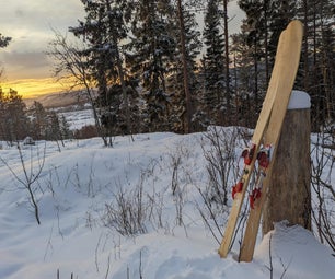
Some of my favorite sledding memories involve the iconic Flexible Flyer runner sleds, which are so common and well-loved in the US that they have virtually become the definition of what a sled is. I wanted to evoke the aesthetic and these classic sleds in my design, which is why I settled on a wooden deck with red skis.
The Skis
The Ski Sled was designed around 135 cm sidecut skis. Most skis of this length are made for young people, which isn't ideal for the weight of an adult. However, I did end up using Jr. skis as the used adult skis I found for sale were quite a bit more expensive. If I used longer skis the sled would be quicker in a straight line, but this increased speed would come at the cost of a wider turning radius.
Step 2: Frame Design and Materials


The ski sled frame was constructed from three aluminum box tubes:
1.25" x 2.5" x 72", 1/8" wall, Aluminum 6063 box
1" x 1" x 72", 1/16" wall, aluminum 6061 box
1.75" x 4" x 12", 1/8" wall, aluminum 6063 box
Approximately half of the 1.25" x 2.5" box tube was used to create the strong, centrally-mounted "backbone" of the sled.
The 1" x 1" box tube was cut into four sections, which pass perpendicularly through the sides of the central box tube. Two of these perpendicular crossbars support the sled above the skis, and all four are used to support the decking. Note that I used an Aluminum 6061 alloy for these box tubes due to their thin, 1/16" walls. My aluminum supplier lists the yield strength of Al 6061 to be approximately double that of Al 6063. During testing of my first sled, I found that 1/16" Al 6063 crossbars would bend during repeated use, while similar Al 6061 box tubes did not.
The remainder of the 1.25" x 2.5" box tube was used to to create the four sloped towers (ski supports), which connect the skis to the crossbars. These ski supports lift the sled comfortably above the snow and allow it to float through powdery conditions.
Finally, the four ski attachment shoes (or pivots), where made from the 1.75" x 4" box tube.
Step 3: Cutting the Frame


All of the cuts for the frame parts were made using my 7 1/4" miter saw. I used an Oshlun, 60 tooth, carbide tipped blade, which is designed for cutting aluminum and other nonferrous metals. Detailed drawings of all of the frame parts can be found in the attached pdf.
The Central Box Tube
The first part cut was the central box tube, which was cut to 35" long. Two 27° bevels were cut on the end of this box, which points towards the front of the sled.
The Crossbars
Next I cut the four 1"x1" crossbars. The front and rear crossbar were cut to 14" in length, while the two middle bars were cut to 15 11/16".
The Ski Supports
The trickiest parts to cut are the four ski supports, which slope downward from the middle cross bars at a 30° angle. There are four cuts required to cut these supports from the 1.25" x 2.5" box tube. The first cut is made at a 4° angle at the bottom end of the support. The second cut is made at 30° and forms the edge, which will lie flush with the top of the cross bar. The third cut is the trickiest as it is made at a 15° angle with respect to the length-wise direction of the box tube. To make this cut, I clamped the box tube length-wise (relative to the miter saw blade) between two 2x4s, which were clamped to the miter saw fence on either side of the box tube. The end of the ski support with the 4° cut was placed against the fence of the miter saw. With the box tube clamped in this position, the saw was mitered to 15° and the long third cut was made through both sided of the box. In order to prevent binding of the blade, the cut was stopped slightly short of the point at which the two pieces would separate. After removing the box tube from the saw, the two pieces were separated by twisting to break the uncut aluminum tab connecting the pieces. The fourth and final cut was made at a 29° angle at the bottom of the ski supports. This cut forms one of the integrated ski pivot stops, which prevent the skis from tipping too far.
The Ski Pivots
The four ski pivots were cut from the 1.75" x 4" box tube. For the front pivots, two 16° cuts were first made through one side of the box, being careful to leave the far side of the box intact. Next, the box tube was flipped and two 37° cuts were made adjacent to the 16° cuts. The side with the 16° cuts is the "tall" side of the front pivots, while the side with the 37° cuts is the "short" side of the pivot. Finally, the box tube was clamped between two 2x4s to allow the tops of the pivots to be trimmed. The short, rear pivots were cut from the box tube in a similar fashion, with 37° cuts being made on both sides of the box tube.
Attachments

Step 4: Finishing the Central Box Tube


After cutting out the frame parts, the specific details (holes, slots, etc.) for each part were completed. I began by finishing the details of the central box tube.
The Handlebar Slot
The sled's handlebar directly bolts to the front of the central box, fitting into a 1.5" deep slot cut into the end of the tube. After roughing out the slot using a hacksaw and Dremel cut-off disk, a metal file was used to smooth the edges of the slot flush with the top and bottom inside surfaces of the box tube. A drill press was used to drill a pilot hole for the handlebar pivot bolt. I like to use undersize pilot holes when drilling large holes in metal. A smaller bit not only cuts through metal more easily, but this technique allows the final hole position to be adjusted if the pilot hole position is slightly off. After drilling the pilot hole through the central box, a 1/2" bit was used to increase the hole's diameter to that of the pivot bolt.
The Crossbar Holes
The four crossbars pass through the central box tube via square holes cut into both sides of the tube. After using a square to precisely align the position of these holes on both sides of the box, two holes were drilled into adjacent corners of each square hole. These holes were sized such that a metal cutting jigsaw blade could start a cut inside of them. Each of the square holes were rough cut to a square shape using the jigsaw. A file was used to precisely finish each hole so that the crossbars would slide through them without being loose. 1/4" holes for bolting the crossbars to the central box were drilled through the top and bottom of the central box using the drill press.
The Cross Link Slot
The final detail added to the central box was a slot cut into the sides of the tube slightly in front of the second crossbar hole. This slot will eventually support the steering cross link, which directly actuates the tie rods leading to the ski pivots. The slot was created by first drilling two holes directly adjacent to one another. A Dremel tungsten carbide cutter was used to connect these holes into a slot. Small metal files were then used to clean up the slot so that it precisely fit the cross link.
Step 5: Finishing the Ski Supports


Since the ski supports bolt around the ends of the two middle crossbars, a slot needs to be cut in each support for the crossbar to lie in. This slot was cut in a fashion similar to that used for the handlebar slot, where a hacksaw was used to cut the sides of the slot with a Dremel cutoff disk completing the closed bottom cut. These slots were carefully finished with a file, with the crossbars sitting flush with the top edges of the supports. Two 13/64" holes were drilled in the top of each support for fastening of the support to the crossbar. A single 5/16" hole was drilled in the bottom of each support for the ski pivot bolt.
Step 6: Finishing the Crossbars


With the ski supports finished, attention turned to the four crossbars, which connect the central box to the decking and ski supports. The middle two crossbars connect to the ski supports, with the front and rear bars supporting the ends of the deck.
First, a 3/16" x 3/4" slot was cut through the center of the front cross bar. This slot allows the inner steering link to pass through the front crossbar. It also helps support the inner link about its pivot bolt. The basic shape of the inner link slot was formed by drilling four, closely spaced holes along the length of the slot. These holes were connected into a rough slot using a Dremel carbide cutter. Finally, a metal file was used to smooth and square the slot.
At this point, the 1/4" deck mounting holes were drilled through the top and bottom of the crossbars using the drill press. Holes for mounting the crossbars to the central box tube were not drilled at this point as they are drilled during final frame assembly.
Attachment of the middle crossbars to the ski supports is one of the most critical points of this build. If each ski support is not precisely aligned and attached, both skis will not align symmetrically with the frame. To ensure perfect alignment, each ski support was clamped around its corresponding crossbar end, with the top of the support lying flush with the top of the crossbar. By clamping the ski support in a vise, I was able to hold the support and crossbar securely together during the next steps. First, the holes in the ski support were used to guide the drill as they were continued through both sides of the crossbar. Next, a 1/4"-20 tap was used to cut threads through both the holes in the ski support and those in the box tube. The motivation for taping these holes was to prevent any movement between the bolts and frame components. Since the ski supports are angled outward at 30°, a torque is introduced on the connection point between support and crossbar. This torque could easily begin to loosen a purely bolted connection, which inherently will have some play between the bolt and hole. A threaded connection is much tighter as the threads directly engage with the hole.
With the holes taped, a 1/4"-20 bolt was tightened into them and secured using a lock washer and nut. At this point in the build, only one side of each crossbar/ski support assembly was bolted together as the crossbars still need to be slid through the square holes in the central box tube.
Step 7: Finishing the Ski Pivots


The four ski pivots (or shoes) attach the skis to the ski supports. A 5/16" pivot bolt joins each ski pivot to its respective ski support and allows each ski to pivot left and right. The holes for this pivot bolt were initially drilled using an undersize bit before being enlarged to their final 5/16" size.
Three 7/32" holes for mounting of the ski pivots to the skis were drilled in the bottom of each pivot. Two holes were drilled on the side of the pivots facing the outside of the skis, with one hole on the inner side. Since the skis are designed to be held in a negative camber position at all times (outside edges up), the outer ski attachment screws will experience more tensile stress than the inner ones. To account for this additional stress, I doubled the number of screws along the outer edges of the skis.
The final hole in the front ski brackets is for the carriage bolt used to attach the steering tie rod ends. This hole was initially drilled using a 1/4" bit before being cut square using both a triangular and flat file. A carriage bolt was used in this location to provide clearance between the head of the bolt and the ski support during turning. After slipping the carriage bolts into their holes, tie rod ends were attached to them with nuts.
Step 8: Assemble the Frame


With the frame components finished, the frame can be assembled. The first step was to drill the crossbar mounting holes in the crossbars. Each crossbar was individually slid through its respective hole in the central box, before being carefully centered across the sled. A square was used to ensure each crossbar was perfectly perpendicular to the central box. The mounting holes in the central box were used as a guide to continue the holes through the crossbars. Although not necessary, each of these holes were undersized and taped using a 1/4"-20 tap. As in the case of the ski support/crossbar connections, my thought was that tapped connections would lead to overall tighter connections.
With the crossbar mounting holes taped, each connection was secured using a 1/4"-20 allen cap head screw, lock washer, and nut. I used stainless steel hardware throughout to ensure the sled would remain rust free for many years.
With the crossbars attached to the central box, the two unattached ski supports were attached using the same bolts, lock washers, and nuts. After assembling the frame, I set it on the floor and jumped on it a few times to test its strength. It passed this test with flying colors.
Step 9: Steering Linkages


There are two links, which connect the handlebar to the tie rods and convert a rotational motion of the handlebar into a linear motion acting on the tie rods. Both of these links were made from 304 stainless steel to both minimize wear at the pivot points and the formation of rust.
The Inner Link
The first link is the inner link, which connects the handlebar to the cross link. This link is made from a 1/2" wide by 3/16" thick 304 stainless steel bar. The first step in making the cross link was to cut this bar to 11.34" in length using a hacksaw. On the one end of the bar was cut the 1/4" wide "pin", which fits into the cross link. After cutting the rough shape of the pin using the hacksaw, a file was used to smooth out the final shape. In the opposite end of the inner link is a short, 1/4" slot, which attaches to the handlebar. This slot was so short that two overlapping 1/4" holes would be required to create it. Overlapping holes are nearly impossible to drill as the bit will fall out of the second hole into the previously-drilled first hole. Knowing this, I first drilled two undersized holes very close together. I then drilled the first 1/4" hole. I did my best to drill the second 1/4" hole through its pilot hole, but eventually had to resort to using the Dremel carbide cutter to finish the slot. The inner link was finished by drilling a 1/4" pivot bolt hole though the center of the inner link.
The Cross Link
The second link is the cross link, which connects the inner link to the tie rods. This link was made from a 1/2" wide by 1/4" thick 304 stainless steel bar. After cutting the bar to a length of 5", the ends were rounded using an angle grinder and file. A 1/4" hole was drilled in both ends of the cross link using the pilot hole, final bit size method. These holes will be used to attach the cross link to the tie rod ends. At the center of the cross link is a square slot, which receives the pin from the inner link. After drilling the initial hole for this slot, it was roughed out using the Dremel and finished into its final rectangular form using small needle files. Note that the side edges of this slot are not cut straight through the bar, but have a convex curve cut into them. See the part drawings for more details. This curve is important as it allows the inner link to pivot slightly in the cross link, while maintaining a tight connection.
Attachments
Step 10: Titanium Glide Plates


I may not have a favorite food or animal, but I have a favorite metal; titanium. This exotic metal has the strength of steel, at a considerably lighter weight. If you're used to handling metal you'll immediately notice the different feel of this metal when you pick it up. It's clearly not steel or aluminum. Over the years I've occasionally made jewelry from Titanium, and I quickly learned that it is extremely hard; so hard that only carbide and diamond tools can machine it.
For the ski sled I was concerned about wear between the hard, stainless steel cross link and the softer, aluminum central box. Since the tie rods attach to the link at an angle, there is a force exerted on the upper and lower edges of the cross link/central box sliding interface as the skis are actuated. In order to prevent wear of the central box, I decided to bolt small, titanium glide plates to the central box tube.
The 1" x 1" glide plates were cut from a 1/16" titanium sheet using a cutoff disk. I've found that cutoff disks are the best method for cutting titanium. The cut plates were clamped together in a vise, with their edges squared using a metal file. Surprisingly, I've found that standard metal files work well on titanium.
The bolt and slot holes were simultaneously drilled through the two plates using carbide drill bits. I use carbide rotary micro bits sold by Harbor Freight. These bits have a 1/8" shank, which fits a Dremel or other rotary tool. After drilling these holes, the rough slot shape was cut using a Dremel carbide cutter, before being accurately finished using small metal files. It's important that the cross link glides smoothly through the plates without excessive play.
Step 11: Handlebar Plates


Two 1/16" aluminum plates are mounted to the top and bottom of the handlebar to both reinforce the pivot point and provide a connection point for the inner steering link. These plates were cut from a 1/16" sheet of 3003 aluminum using my miter saw. Given the large number of angles of these plates, multiple cuts at different angles were required to arrive at the finished plate shape. The edges of the plates were cleaned up using a metal file.
Each plate is attached to the handlebar via two bolts, which pass through 1/4" holes drilled at each end of the plate. A 3/4" hole was drilled in the center of each plate. This hole allows the 1/2" handlebar pivot bolt and a concentric nylon spacing washer to pass through the plate. Finally, two holes for attachment of the inner link were drilled into the ends of the plate tabs. A 1/4" hole was made through the top plate with a 13/64" hole in the bottom plate.
Since the handlebar is 7/8" thick and the inner link 3/16" thick, both of the plate tabs were bent together using a Vise Grip sheet metal tool. The angled portion of the plate tab was bent to approximately 25° relative to the top of the plate.
Step 12: The Handlebar


The handlebar and decking were made from a 1" rough cut walnut board. A 22" length of the board was used to make the handlebar. This board was planed until it easily slid into the central box handlebar slot, while sandwiched between the two aluminum handlebar plates. The handlebar is approximately 7/8" thick. Next, the shape of the handlebar was cut from the board using a jigsaw.
To give the handlebar a smooth, gripable surface, the edges were rounded using a 1/4" roundover router bit. Some light sanding finished this edge. On the rear of the handlebar, a 25° bevel was shaped with a belt sander. This bevel provides support for the handlebar plates as they make the transition from the handlebar thickness to the inner link thickness.
The handlebar plate mounting holes were drilled by first clamping the handlebar between the two plates. Using the holes in one plate as a guide, 1/4" holes were drilled halfway through the handlebar. These holes were completed through the handlebar by drilling from the opposite side. This method ensures that the plates and handlebar are in perfect alignment.
Drilling of the handlebar pivot hole was completed in three steps. First, an 1/8" pilot hole was drilled to mark the position of the pivot hole. Using the pilot hole as a guide, a 3/4" forstner bit was used to create a slight recess on both sides of the handlebar. These recesses will house the nylon spacer fitted around the pivot bolt. Finally, the 1/2" pivot hole was drilled through the handlebar using the pilot hole as a guide.
Step 13: Decking


The decking was made from the remainder of the board used for the handlebar. After a slight plane, a square board was ripped off one side of the board. This resulting square board was cut into two lengths of 25.625", creating the two deck rails. All of the deck rail edges were rounded using the 1/4" roundover router bit.
Next, a 3.75" wide board was ripped from the walnut board. Since the deck boards are around 1/4" thick, they can be made by ripping the 3.75" wide board in half vertically. To make this cut, the table saw fence was moved such that the blade would perfectly bisect the board when in a vertical orientation. The blade was raised so that it cut approximately half way through the board. After ripping the board halfway through, it was flipped and the other half was ripped, separating the two halves.
This is a dangerous cut for several reasons. First, since the blade is entirely contained within the board, the kickback risk is increased. Second, the narrowness of the vertical board requires that the operator work closer to the blade. I made sure to stand out of the way in case of kickback and used a pusher block when my hand would have been close to the blade. I did not encounter any problems and was rewarded with two, albeit rough, deck boards.
I gave the deck boards a quick plane to remove any imperfections produced during cutting. Finally, the deck boards we cut to 30.09" in length with each end mitered to 28°.
I finished all of the wood with Danish oil. I like Danish oil as it is not only easy to apply, but for this application I don't have to worry about moisture working its way under a hard finish like polyurethane. Over time the oil will wear off, but it can be easily re-applied in a matter of minutes.
Step 14: Attach the Decking to the Frame


In preparation of drilling the decking mounting holes, the deck boards and rails were laid out on the frame. Next, the frame and decking were flipped and realigned such that the mounting holes in the crossbars could be used to mark the hole positions in the wood. After the deck rails were aligned, their mounting hole positions were marked by drilling through the crossbars and partially into the wood. The "marked" deck rails were removed from the frame and the 1/4" mounting holes were finished using the drill press. Hole positions for the deck boards were similarly marked before being drilled with the drill press. With all of the deck mounting holes drilled, the boards and rails were bolted to the crossbars using 1/4"-20 allen head cap screws, lock washers, and nuts.
Step 15: Attaching the Skis


I used a pair of 135cm junior skis that I found on Craiglist for $10. I spray painted the skis red, which I think really contrasts nicely with the white of the snow and dark brown of the walnut deck.
Before attaching the skis to the pivots (shoes), the pivots are attached to the ski supports using 1.75" long 5/16" shoulder screws. Washers placed between the pivots and ski supports remove slack between these components. Each shoulder screw was secured using a lock washer and nut.
With the pivots fastened to the frame, the frame was aligned over the skis and the mounting hole locations were marked with a bit. Drilling screw holes in skis feels like a game of chicken as you want to go as deep as possible without drilling through the base surface of the ski. To remove the guesswork, I set the drill press depth stop such that the bit would stop a few millimeters shy of the bottom surface. With the depth set, I drilled the screw pilot holes with a 9/64" bit.
After repositioning the skis under the frame, they were secured to the pivots using binding screws. Although not shown in the pictures, installation of the inner screws required removal of the pivot bolts.
Step 16: Assemble the Steering


The last step of this build was to assemble the steering system. First, the cross link was inserted through the titanium glide plates and through the slot in the central box. The inner rod was secured to the tabs of the handlebar plates using a 1/4" x 1/4" long shoulder screw and 10-24 lock nut. Next, this inner rod, handlebar assembly was slid into the central box with the inner rod passing through the slot in the first crossbar. In order for the handlebar to fully slide into the central box, the pin at the end of the inner link must slide into the rectangular slot in the middle of the cross link. Once everything slides together properly, the handlebar is secured to the central box using a 1/2" x 1.25" long shoulder screw, which serves as the handlebar pivot. The centrally-located front crossbar/inner link pivot bolt is re-installed through the inner link pivot.
With the handlebar and inner link secured, all that remains is installation of the tie rods between the crosslink and the outer tie rod ends on the front pivots. The tie rods were made from a section of 1/4-28 threaded rod, with clevis style rod ends used as the inner tie rod ends. These particular clevis joints have hand removable pins, which makes tie rod length adjustments quick and easy.
Step 17: Testing


With the ski sled finished, all that remained was the wax the skis and hit up a snow covered road. Unfortunately, where live in eastern Pennsylvania can be quite hit or miss in the snow department. Eventually though, we were blessed by a few inches of the white stuff and I made the short drive up to the mountain.
The road I sled has over a 650 foot elevation change over 1.2 miles, which is steep enough to pick up good speed without it feeling out of hand. There are two, sharp 180° hairpins and two moderate corners. On the day I tested the MKII sled, conditions were not ideal as the snow cover was really too thin, and I cut through to the stones the entire way down. Because of this, I was only able to achieve a top speed slightly in excess of 20 mph.
As for the steering performance, I was able to take all of the corners without braking. However, I still found the steering performance to be not as good as I would have liked. I believe one contributing factor was the very dull edges of the skis. I'm currently re-sharpening the edges in preparation for the next run. I was impressed by the precision of the steering using my new double-link setup. An actuation of the handlebar corresponded to a direct movement of the skis that was not vague in the least.
One thing I was left missing from my previous sled was suspension. I had no idea how many bumps the suspension on the MKI sled was removing. By the time I reached the bottom of the mountain, I was sore and had a slight headache from all the jarring. Never again will I think of suspension on a sled as a needless luxury.
I'm currently waiting for more snow to visit our region so that I can test the sled further. As I conduct these tests I will update this section, so check back if you're interested to see how things pan out.

Grand Prize in the
Snow Challenge