

Introduction: DUAL MODE ROBOT => (AUTONOMOUS / MANUAL CONTROL)


DTMF or dual tone multi frequency is nifty little way of controlling machines with your cellphone. This instructable shows you, gentle reader how to make a cheaper than dirt DTMF controlled robot that can also function AUTONOMOUSLY, yeh! that's right AUTONOMOUSLY when things get tight.
The project is built around the Oh-so-versatile Arduino UNO (Oh arduino is their anything you can't do!!!!!!).
The programming is straight forward but make sure everything is on hand before you start tinkering.
The entire project can be slapped together for less than 50$ and can bring hours of mindless fun to you and the family pet.
Step 1: STUFF YOU NEED


1:- DTMF Module (http://www.ebay.in/itm/like/20119037796).
2:- ARDUINO UNO.
3:- JUMPER WIRES (MALE TO FEMALE and MALE TO MALE).
4:- PING ULTRASONIC SENSOR (YOU CAN USE HC-SR04 SENSOR TOO BECAUSE IT IS CHEAPER BUT YOU HAVE TO MODIFY THE CODE WHICH I WILL EXPLAIN IN THE CODE SECTION).
5:- 2 I.R. SENSOR (http://www.amazon.in/ROBOSOFT-SYSTEMS-Single-Sensor-Module/dp/B00U3LKGTG/ref=sr_1_cc_3?s=aps&ie=UTF8&qid=1427820514&sr=1-3-catcorr&keywords=ir+sensor+module)
6:- 2 SMALL BREAD BOARDS.
7:- L293D MOTOR DRIVER(http://www.amazon.in/L293D-Push-Pull-Four-Channel-...) YOU CAN ALSO USE THE L293D MODULE AVAILABLE AT(http://www.ebay.in/itm/like/271552019152)
8:- 2 WHEELS AND 2 STEPPER MOTORS WITH THE GEARBOX(AVAILABLE ON AMAZON) IF YOU USE THE MOTORS WITHOUT THE GEAR BOX THEN THEY WILL NOT BE ABLE TO PROVIDE ENOUGH TORQUE TO MOVE THE WHEELS WHEN THE ROBOT IS PLACED ON GROUND. "PERSONAL EXPERIENCE!!!!!!"
9:- ONE MOBILE PHONE WITH 3.5mm JACK SUPPORT, AND ONE FOR CALLING.
10:- SMALL BOX.
11:- DOUBLE SIDED TAPE.
Step 2: GETTING STARTED: CONNECTING DTMF With Arduino


For those of you who are not familiar with DTMF, I have given a link below, please do check.
http://www.mediacollege.com/audio/tone/dtmf.html
Connect There are 4 pins on one side of the DTMF controller marked as D0, D1, D2, D3, connect these pins to the pin 3, 4, 5 & 6 of Arduino respectively i.e. D0 to pin 3, and so on. We will be drawing power for the DTMF from the Arduino. I will tell you how in the 4th step.
Step 3: SETTING THE L293D

The advantage of using a motor driver and stepper motors is that this arrangement is cheaper compared to using Servo motors.
Connect the pins 4, 5, 12, 13 together using small jumpers. You can make these jumpers using solid core aluminium wires. Connect the pins 1 and 9 together and pins 8 and 16 together. Connect the pin:
ARDUINO <=========> DRIVER
pin 9 <----------------------------> pin 2
pin 10 <--------------------------> pin 7
pin 11 <--------------------------> pin 15
pin 12 <--------------------------> pin 10
Connect the 5V from arduino to the pin 1 through bread board, and GND to the pins 4 , 5, 12, or 13, any one will do.
Step 4: CONNECTING THE SENSORS WITH ARDUINO


The sensor I am using is a PING ultrasonic sensor due to it's high reliability and lower pin count compared to HC-SR04 which is a 4 pin sensor, as it has separate pins for input and output signal, while ping uses the same pin for input and output. Also I got it for free so why to buy another!!!!!!
I will tell you how to modify the code for 4 pin sensor later in the code section. Output means that the sensor module will be excited by the Arduino to fire the ultra sonic pulse, and input means that the reflected wave sensed by the sensor is input to the Arduino. Connect the signal pin to the pin 8 on Arduino.
Since we have to use a limited number of power source we will be drawing power from the Arduino;
So connect the 5V pin of the sensor to the driver breadboard's 5v supply (FROM THE ARDUINO), and GND to the ground of driver board. If you are using a driver module, make a common 5V take off point and ground connection for these two. Also connect the power supply pin of the DTMF module to the bread board power supply.
Similarly connect the output pins of the I.R. sensor to the pin 11 and 12 according to the code.
Step 5: CONNECTING THE 5 BABIES WITH MOTHER

Now connect all the five modules to the Arduino.
Step 6: THE CODE

The coding was a challenge, since the DTMF can generate code for only one digit at a time.
The problem was coding for the manual mode where I had to define a key for switching to manual mode. I will explain with an example:-
void loop()
{ int z = digitalRead(d0);
int y = digitalRead(d1);
int x = digitalRead(d2);
int w = digitalRead(d3);
if((w == LOW)&&(x == LOW)&&(y == LOW)&&(z == HIGH)) i.e. digit 1
{ if((w == LOW)&&(x == LOW)&&(y == HIGH)&&(z == LOW)) i.e. digit 2
The code should work like this :- if 1 is pressed, the robot goes into manual mode and by pressing 2 on the keypad the robot moves forward. But what actually happens is that as I press 2 the robot is no longer in manual mode. WHY??????
The answer is that, the state at the pins of Arduino connected to the DTMF have changed now, i.e. they are no longer 1, because the state information is not stored anywhere (because the state has to change when the robot is switched to autonomous mode and the DTMF also can generate only code for last pressed key and can not store, the code itself).
THE SOLUTION:- The solution was simple, instead of placing a condition for a number, for switching the mode, I had placed it for a digit:-
Example:-
if(w == LOW)
{ if((w == LOW)&&(x == LOW)&&(y == HIGH)&&(z == LOW))
{ digitalWrite(motorL1, HIGH);
digitalWrite(motorL2, LOW);
digitalWrite(motorR1, HIGH);
digitalWrite(motorR2, LOW);}
if((w == LOW)&&(x == HIGH)&&(y == LOW)&&(z == HIGH))
{ digitalWrite(motorL1, LOW);
digitalWrite(motorL2, HIGH);
digitalWrite(motorR1, LOW);
digitalWrite(motorR2, HIGH); }
if((w == LOW)&&(x == HIGH)&&(y == LOW)&&(z == LOW))
{ digitalWrite(motorL1, LOW);
digitalWrite(motorL2, HIGH);
digitalWrite(motorR1, HIGH);
digitalWrite(motorR2, LOW); }
if((w == LOW)&&(x == HIGH)&&(y == HIGH)&&(z == LOW))
{ digitalWrite(motorL1, HIGH);
digitalWrite(motorL2, LOW);
digitalWrite(motorR1, LOW);
digitalWrite(motorR2, HIGH); }
if((w == LOW)&&(x == HIGH)&&(y == HIGH)&&(z == HIGH))
{ digitalWrite(motorL1, LOW);
digitalWrite(motorL2, LOW);
digitalWrite(motorR1, LOW);
digitalWrite(motorR2, LOW); }
}
SINCE 'W' WILL ALWAYS STAY LOW FOR THE ABOVE DIGITS, THE W=0 CONDITION WILL BE TRUE THROUGHOUT.
Step 7: THE CODE :- FOR PING SENSOR
<p>const int serialPeriod = 250;   // a period of 250ms = a frequency of 4 Hz <br>unsigned long timeSerialDelay = 0;</p><p>const int UltraloopPeriod = 20;        // a period of 20ms = a frequency of 50 Hz
unsigned UltraLoopDelay = 0;</p><p> const int sensor_1 = 10;                 // input/output from the sensor_1


 int motorL1 = 6;                               // output for motor driver pin 2
 int motorL2 = 7;                               // output for motor driver pin 7

 int motorR1 = 8;                              // output for motor driver pin 15
 int motorR2 = 9;                              // output for motor driver pin 10

 int d0 = 2;                                        // input from DTMF pin D0
 int d1 = 3;                                        // input from DTMF pin D1
 int d2 = 4;                                        // input from DTMF pin D2
 int d3 = 5;                                        // input from DTMF pin D3

 int ultrasonicTime;                          // variable to store time
 int ultrasonicDistance;                    // variable to store distance calculated

 void setup()
{
   Serial.begin(9600);                       // setting serial communication speed

   pinMode(motorL1, OUTPUT);
   pinMode(motorL2, OUTPUT);
   pinMode(motorR1, OUTPUT);
   pinMode(motorR2, OUTPUT);

   pinMode(d0, INPUT);
   pinMode(d1, INPUT);
   pinMode(d2, INPUT);
   pinMode(d3, INPUT);
}</p><p>void loop()
{
  int z = digitalRead(d0);
  int y = digitalRead(d1);
  int x = digitalRead(d2);
  int w = digitalRead(d3);

  /*----------------------------------------- M A N U A L    M O D E ---------------------------------------*/

  if(w == LOW)
  {
    if((w == LOW)&&(x == LOW)&&(y == HIGH)&&(z == LOW))
    {
      digitalWrite(motorL1, HIGH);
      digitalWrite(motorL2, LOW);
      digitalWrite(motorR1, HIGH);
      digitalWrite(motorR2, LOW);
    }

    if((w == LOW)&&(x == HIGH)&&(y == LOW)&&(z == HIGH))
    {
      digitalWrite(motorL1, LOW);
      digitalWrite(motorL2, HIGH);
      digitalWrite(motorR1, LOW);
      digitalWrite(motorR2, HIGH);
    }

    if((w == LOW)&&(x == HIGH)&&(y == LOW)&&(z == LOW))
    {
      digitalWrite(motorL1, LOW);
      digitalWrite(motorL2, HIGH);
      digitalWrite(motorR1, HIGH);
      digitalWrite(motorR2, LOW);
    }

    if((w == LOW)&&(x == HIGH)&&(y == HIGH)&&(z == LOW))
    {
      digitalWrite(motorL1, HIGH);
      digitalWrite(motorL2, LOW);
      digitalWrite(motorR1, LOW);
      digitalWrite(motorR2, HIGH);
    }

     if((w == LOW)&&(x == HIGH)&&(y == HIGH)&&(z == HIGH))
    {
      digitalWrite(motorL1, LOW);
      digitalWrite(motorL2, LOW);
      digitalWrite(motorR1, LOW);
      digitalWrite(motorR2, LOW);
    }
  }

   /*----------------------------------- A U T O N O M O U S    M O D E -----------------------------------*/


  if(w == HIGH)
  {
    viewDistance();

    if((millis() - UltraLoopDelay) >= UltraloopPeriod)
    {
      readUltrasonicsensor_1();
      motorStart();
      UltraLoopDelay = millis();
    }
  }
 }
void readUltrasonicsensor_1()                               // fuction to take sensor_1 data and find distance
{
   pinMode(sensor_1, OUTPUT);
   digitalWrite(sensor_1, LOW);
   delay(2);
   digitalWrite(sensor_1, HIGH);
   delay(10);
   digitalWrite(sensor_1, LOW);

   pinMode(sensor_1, INPUT);
   ultrasonicTime = pulseIn(sensor_1, HIGH);
   ultrasonicDistance = (ultrasonicTime/2)/29;      //calculation to measure the distance of obstacle from ultrasoni                                                                                // c sensor
}</p><p>void motorStart()                                                    //function to drive the motor according to sensed distance
{


   if(ultrasonicDistance > 10)
   {


         digitalWrite(motorL1, HIGH);
         digitalWrite(motorL2, LOW);
         digitalWrite(motorR1, HIGH);
         digitalWrite(motorR2, LOW);
       }
      if((irsL == HIGH)&&(irsR == LOW))
       {
         digitalWrite(motorL1, HIGH);
         digitalWrite(motorL2, LOW);
         digitalWrite(motorR1, LOW);
         digitalWrite(motorR2, HIGH);
       }

     if((irsL == LOW)&&(irsR == HIGH))
       {
         digitalWrite(motorL1, LOW);
         digitalWrite(motorL2, HIGH);
         digitalWrite(motorR1, HIGH);
         digitalWrite(motorR2, LOW);
       }

      if((irsL == HIGH)&&(irsR == HIGH))
       {
         digitalWrite(motorL1, LOW);
         digitalWrite(motorL2, HIGH);
         digitalWrite(motorR1, LOW);
         digitalWrite(motorR2, HIGH);
       }

   }

   if(ultrasonicDistance < 10)
   {
         digitalWrite(motorL1, LOW);
         digitalWrite(motorL2, HIGH);
         digitalWrite(motorR1, HIGH);
         digitalWrite(motorR2, LOW);
       }


   }
}</p><p>/*---------------------------CHECKING THE ULTRSONIC SENSOR-------------------------*/</p><p>void viewDistance()                                             //function to view distance on serial monitor
{                                                                            //to check if the ultra sonic sensor code working properly
  if((millis() - timeSerialDelay) >= serialPeriod)
  {
    Serial.print("Distance");
    Serial.print(ultrasonicDistance);
    Serial.print("cm");
    Serial.println();

    timeSerialDelay = millis();
  }
}</p>
Step 8:
Step 9: THE CODE :- FOR THE HC-SR04 SENSOR
<p>I have made few corrections(marked as {CORRECTIONS}) and added some new lines({marked as {ADDED}}) FOR HC-SR04. </p><p><br>
<p>const int serialPeriod = 250; // a period of 250ms = a frequency of 4 Hz <br>unsigned long timeSerialDelay = 0;</p><p>const int UltraloopPeriod = 20; // a period of 20ms = a frequency of 50 Hz
unsigned UltraLoopDelay = 0;</p><p> const int sensor_1_in = 10; // input from the sensor_1
const int sensor_1_out = 13; // output from the sensor_1
int motorL1 = 6; // output for motor driver pin 2
int motorL2 = 7; // output for motor driver pin 7
int motorR1 = 8; // output for motor driver pin 15
int motorR2 = 9; // output for motor driver pin 10
int d0 = 2; // input from DTMF pin D0
int d1 = 3; // input from DTMF pin D1
int d2 = 4; // input from DTMF pin D2
int d3 = 5; // input from DTMF pin D3
int ultrasonicTime; // variable to store time
int ultrasonicDistance; // variable to store distance calculated
void setup()
{
Serial.begin(9600); // setting serial communication speed
pinMode(motorL1, OUTPUT);
pinMode(motorL2, OUTPUT);
pinMode(motorR1, OUTPUT);
pinMode(motorR2, OUTPUT);
pinMode(d0, INPUT);
pinMode(d1, INPUT);
pinMode(d2, INPUT);
pinMode(d3, INPUT);
}</p><p>void loop()
{
int z = digitalRead(d0);
int y = digitalRead(d1);
int x = digitalRead(d2);
int w = digitalRead(d3);
/*----------------------------------------- M A N U A L M O D E ---------------------------------------*/
if(w == LOW)
{
if((w == LOW)&&(x == LOW)&&(y == HIGH)&&(z == LOW))
{
digitalWrite(motorL1, HIGH);
digitalWrite(motorL2, LOW);
digitalWrite(motorR1, HIGH);
digitalWrite(motorR2, LOW);
}
if((w == LOW)&&(x == HIGH)&&(y == LOW)&&(z == HIGH))
{
digitalWrite(motorL1, LOW);
digitalWrite(motorL2, HIGH);
digitalWrite(motorR1, LOW);
digitalWrite(motorR2, HIGH);
}
if((w == LOW)&&(x == HIGH)&&(y == LOW)&&(z == LOW))
{
digitalWrite(motorL1, LOW);
digitalWrite(motorL2, HIGH);
digitalWrite(motorR1, HIGH);
digitalWrite(motorR2, LOW);
}
if((w == LOW)&&(x == HIGH)&&(y == HIGH)&&(z == LOW))
{
digitalWrite(motorL1, HIGH);
digitalWrite(motorL2, LOW);
digitalWrite(motorR1, LOW);
digitalWrite(motorR2, HIGH);
}
if((w == LOW)&&(x == HIGH)&&(y == HIGH)&&(z == HIGH))
{
digitalWrite(motorL1, LOW);
digitalWrite(motorL2, LOW);
digitalWrite(motorR1, LOW);
digitalWrite(motorR2, LOW);
}
}
/*----------------------------------- A U T O N O M O U S M O D E -----------------------------------*/
if(w == HIGH)
{
viewDistance();
if((millis() - UltraLoopDelay) >= UltraloopPeriod)
{
readUltrasonicsensor_1();
motorStart();
UltraLoopDelay = millis();
}
}
}
void readUltrasonicsensor_1() // CHANGED
{
digitalWrite(sensor_1_out, LOW);
delay(2);
digitalWrite(sensor_1_out, HIGH);
delay(10);
digitalWrite(sensor_1_out, LOW);
ultrasonicTime = pulseIn(sensor_1_in, HIGH);
ultrasonicDistance = (ultrasonicTime/2)/29; // calculation to measure the distance of obstacle from ultrasoni // c sensor
}</p><p>
void motorStart() // function to drive the motor
{
if(ultrasonicDistance > 10) /
{
digitalWrite(motorL1, HIGH);
digitalWrite(motorL2, LOW);
digitalWrite(motorR1, HIGH);
digitalWrite(motorR2, LOW);
}
if(ultrasonicDistance < 10)
{
{
digitalWrite(motorL1, HIGH);
digitalWrite(motorL2, LOW);
digitalWrite(motorR1, LOW);
digitalWrite(motorR2, HIGH);
}
}
}</p><p>/*---------------------------CHECKING THE ULTRSONIC SENSOR-------------------------*/</p><p>
void viewDistance()
{
if((millis() - timeSerialDelay) >= serialPeriod)
{
Serial.print("Distance");
Serial.print(ultrasonicDistance);
Serial.print("cm");
Serial.println();
timeSerialDelay = millis();
}
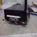
}</p>Step 10: PREPARING THE BODY OF THE ROBOT !!!!!!


The hole on the box in 1st image has nothing to do with anything.
1: Take an ordinary Cardboard box drill some holes for the motor shaft with thick body pen.
2: Place the motors using the double sided tape or with any other feasible method you like.
Step 11: In Continuity......

For the sensor you have to make a few adjustments shown above. The only reason for using small jumpers was that the sensor was taking more space than I thought, so I had to place most of the breadboard outside. It's bit complicated to explain but you will understand what's going on when you reach this point in the build.
Any way, you can use other techniques that suit your fancy for placing the sensor on the robot, but what I tried to do was placing all the wires inside, with no wires outside the box. also you can mount the sensor straight if you wish. But make sure the sensor is not too high or else it will not be able to detect objects of smaller height.
Step 12: TESTING......

Place the mother and it's babies in side the box and do a test run WITHOUT WHEELS.
No need to say the DTMF is missing, it's just hanging out.
According to the code I have written :-
2 = forward
5 = backward
4 = left turn
6 = right turn
digit other than 1, 2, 3, 4, 5, 6 and 7 will put the robot in Autonomous mode.
Step 13: CLOSING THE HOOD

Now it's time to place everything inside the body close the hood AND......PLAY!!!!!!
ALL THE BEST......

Participated in the
Microcontroller Contest


