

Introduction: Arduino Automatic Motion Detection Activated Lamp With PIR Sensor on Tinkercad Simulation


In this project, we are going to learn how to make Arduino circuit that automatically controls a lamp using motion sensor.
This type of sensor is called PIR Passive Infrared. Here, we build the circuit inside Tinkercad Simulation Environment and then simulate its action just as in the real world.
Also, we used Tinkercad CodeBlocks feature to generate Arduino code that can be uploaded into the ATtiny85 Microcontroller.
Supplies
We are going to build the circuit inside Tinkercad Simulation Environment. So, all we actually need is a PC, internet connection and Tinkercad Account.
But since we are building a virtual circuit that can be directly transformed into a real-world circuit using the same components and software, then we are going to list all circuit parts and components.
And you can follow those steps to build your own circuit. This circuit can be used in front of your door or patio to detect motion and light the lamp automatically.
I’ve seen this circuit in action and it’s very useful when you try to reach your door in the dark and cannot find the light switch.
Components used:
PIR Passive Infra Red Sensor Amazon
ATiny85 Amazon
7895 5V voltage regulator
1kOhm Resistor
2N2222 NPN BJT Transistor
9V Battery
Light Bulb
Jumper Wires for Connections
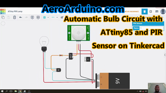
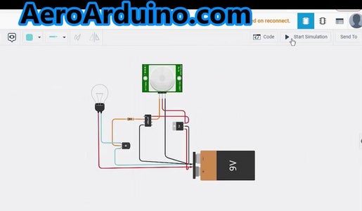
Step 1: Circuit Connection


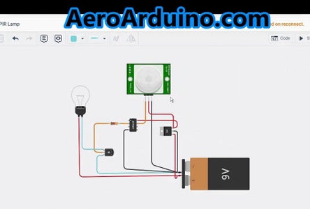
You can see the circuit connection inside Tinkercad Model as real components and you can also see the schematic view of the circuit when you press the Schematic view on the upper right corner in Tinkercad Model.
Circuit connection is as follows:
9V batter is connected to the 5V regulator into the input PIN and to one of the lamp terminals.
Output of the 5v regulator is connected to PIR Sensor Supply PIN and to ATtiny85 Power PIN.
Output of the PIR Sensor is connected to ATtiny85 AN1 Pin called PB2.
ATtiny85 PIN PB1 connected to 1Kohm resistor.
The other terminal of the resistor is connected to the Base of the Transistor.
Collector Terminal of the Transistor is connected to the other terminal of the Lamp.
Emitter Terminal of the Transistor is connected to the Negative Terminal of the 9V battery.
9v Battery Negative terminal is connected to the Ground Pins of the ATtiny85 Microcontroller, PIR Sensor and 7805 voltage regulator.
Step 2: Code Blocks
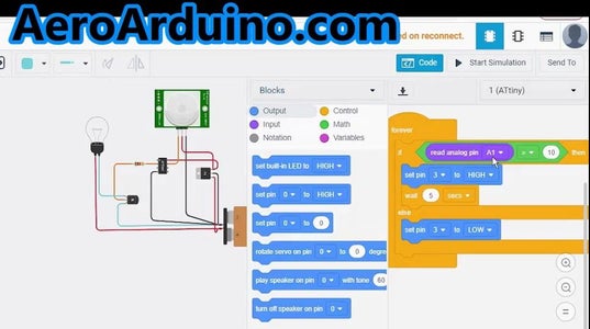

In Tinkercad website, we press the code button to get the blocks view.
We choose the Yellow Control Button to get the Forever function and place it inside the blocks area.
Then also from the Control category we click and drag the IF/Then/Else block.
We choose Math category and choose the Compare block and put it inside the IF condition.
Choose Input category and choose Read Analog Pin block.
Configure it to PIN A1.
Configure the Compare block to greater than or equal to the Read Analog Pin side.
Write the comparison value to 10.
Inside the Then statement we insert Set Pin block from the Output category.
Configure it to Pin 3 and HIGH.
From the Control category, we choose Wait block and write down 5 seconds.
In the Else statement, we insert Set Pin block and configure it to Pin 3 and LOW.
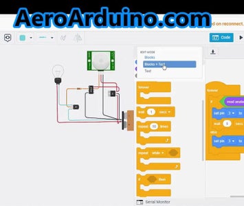
Step 3: Software Code

Inside the Tinkercad environment, we press the Blocks Button and choose Blocks + Text from the drop down menu.
We now can see the automatically generated Arduino code that we can directly upload to Physical Arduino Board or ATtiny85 Microcontroller IC.
void setup()
{
pinMode(A1, INPUT);
pinMode(3, OUTPUT);
}
void loop()
{
if (analogRead(A1) >= 10 ) {
digitalWrite(3, HIGH);
delay(5000); //Wait for 5000 millisecond(s)
} else {
digitalWrite(3, LOW);
}
}
Attachments

Step 4: Tinkercad Simulation

We can see the circuit in action simulation by pressing the Start Simulation Button in Tinkercad website.
To simulate motion in front of the PIR Sensor, we first click it to be selected.
Then we can find a circle target and a conical shaped area that presents the detection area of the sensor.
When the target is moved inside the detection area, the PIR sensor senses the motion and sends a signal to ATtiny85 and then it sends a signal to the Transistor to light the Lamp.
Then after 5 seconds from the target motion detection, the Lamp goes off again if there’s no motion detected.
Step 5: Tinkercad Model
Here is the Tinkercad Model with Circuit and Code.
You can start interacting with it and you can copy it, use it or edit it on your Tinkercad Account.
Step 6: Videos
Here’s the video on AeroArduino Channel on YouTube.
Please like, share and subscribe.
You can find this project and many more on AeroArduino.com Blog Here.
Thank you for visiting my project.

Participated in the
Electronics Contest


