

Introduction: Arduino Experiments (Supersize Instructable)


- Masses if not all Arduino Experiments done my way,that being everyone carry's out experiments different to the next person,as such this instructable will have alot of videos,and pictures as well as detailed descriptions of each experiment what I did how and why....
- LARGE INSTRUCTABLE BE WARNED!
- (there are many arduino instructables on such things,however this will be a very large instructable with many step's,subject to changes and updates)
Step 1: Part's Needed.


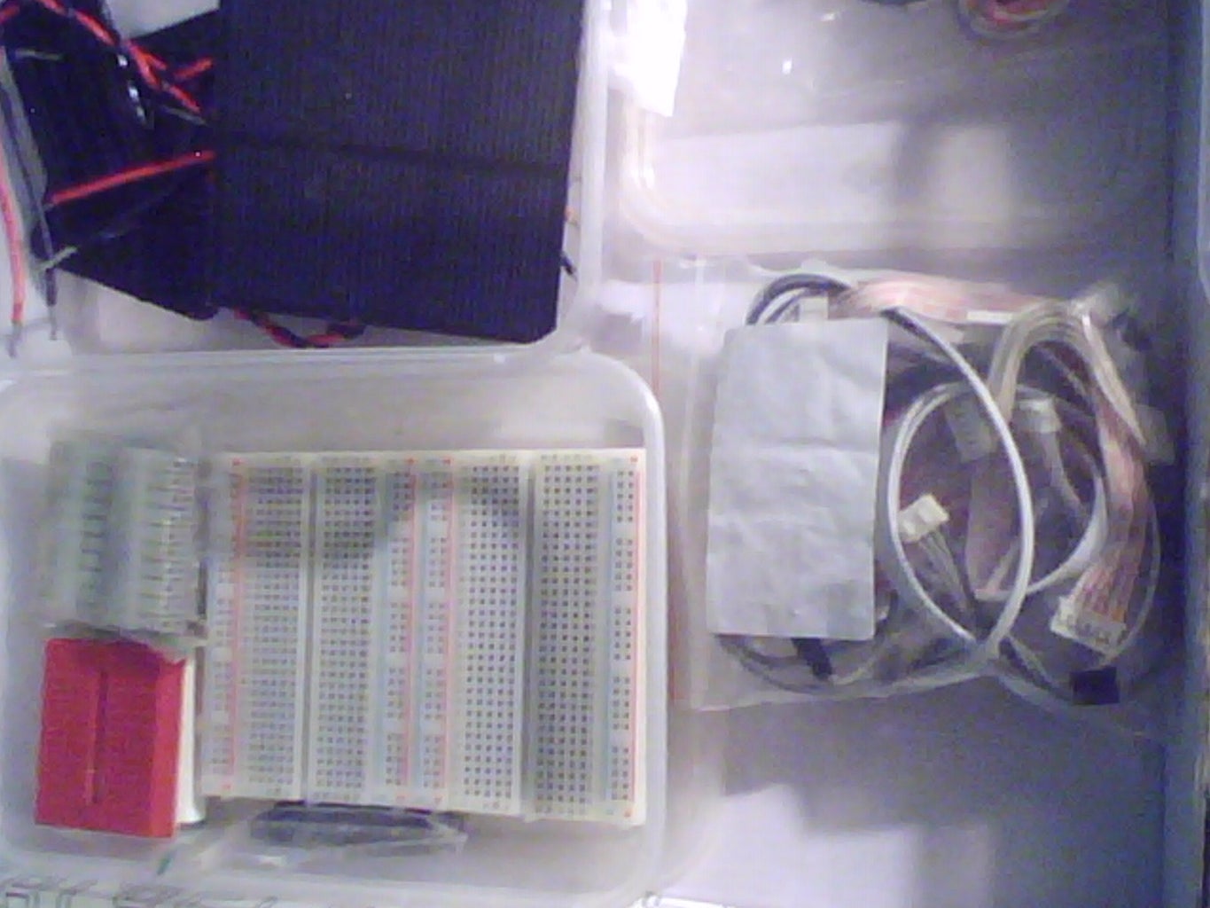

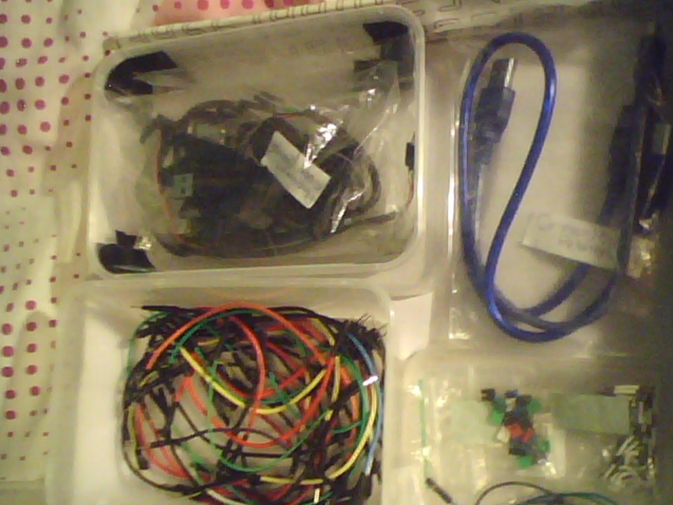
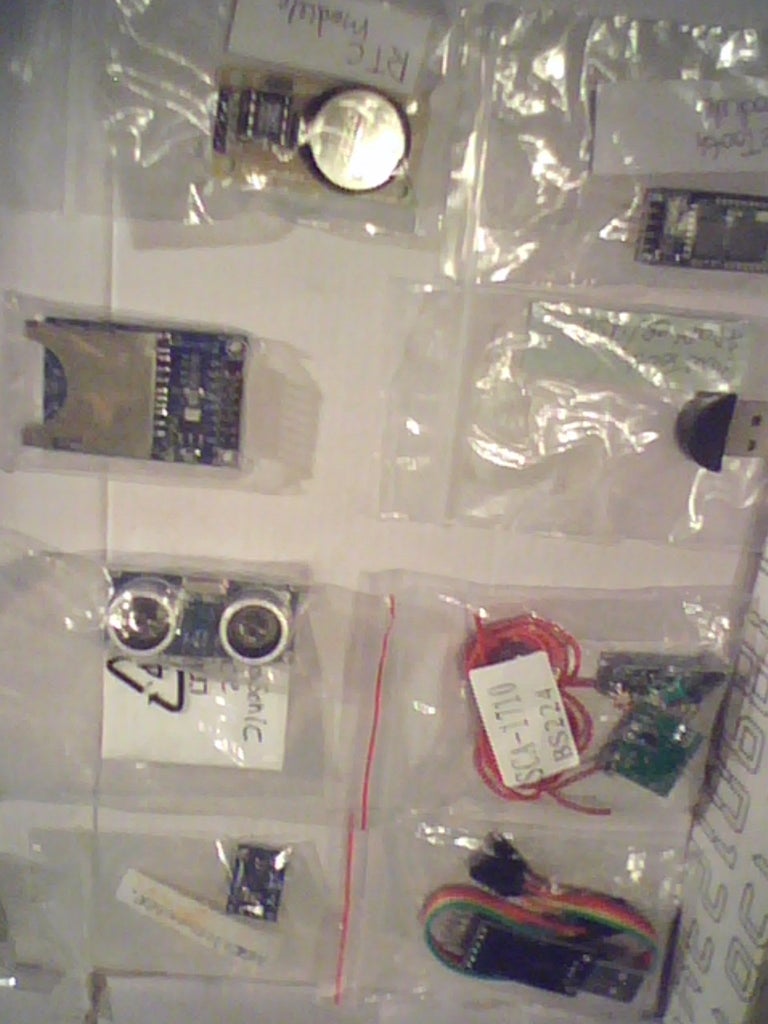


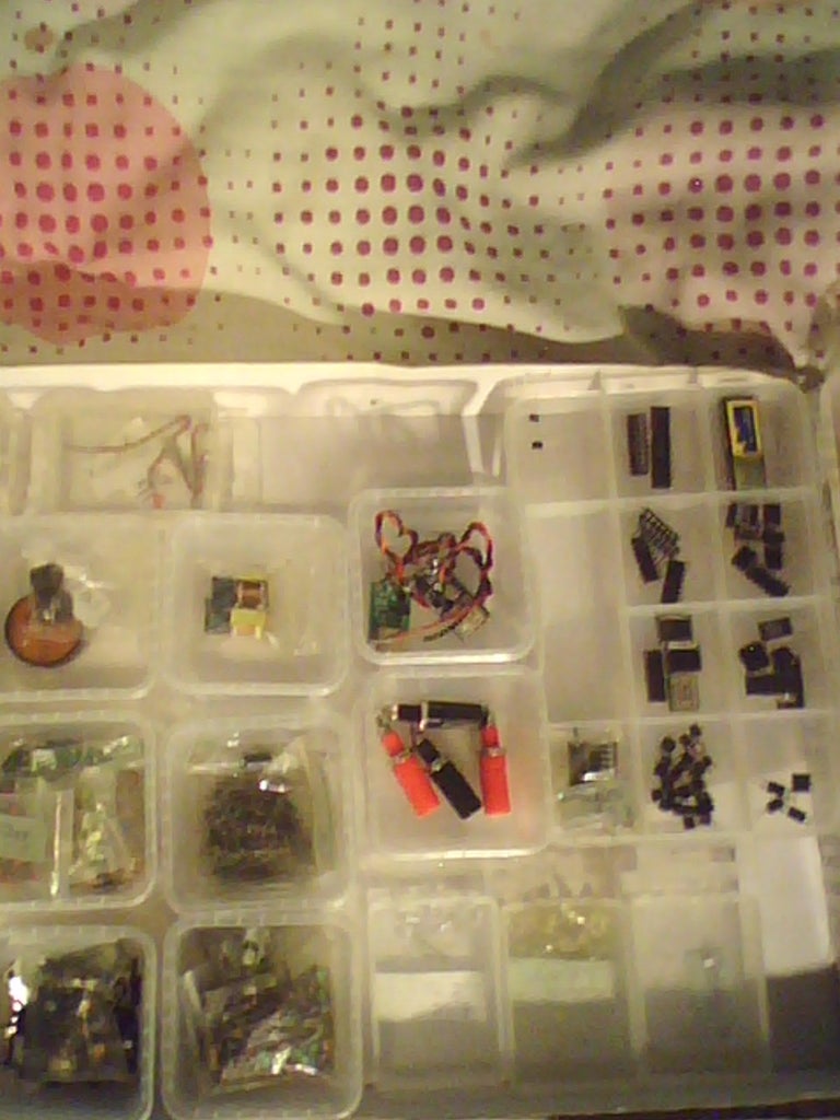


List and pictures of all parts,tools & Components used in this Instructable... (Any additional spares you have in your electronics box will likely help if your first time making Various Arduino Projects & Tests.)
This huge list of parts and images must seem overwhelming to say the least,but do not worry alot of these are for reference alot of tools can be improvised or scavenged like Switches & LED's Capacitors Transistors and so on,While others are must have's such as Solder-less breadboards,arduino boards and accompanying equipment/parts,etc Servos,LCD Screens,Jumper Wires.
Recycling as many parts as you can is advisable to cut down costs on projects,while being green at the same time,solar or alternative power recommended where usable,as most boards can be powered with a couple of rechargeable battery's.
Step 2: Tool's Needed (some Optional)


Tools that can help with projects and with making custom parts,as well as testing your recycled (?) components as some may be damaged or not work at all and need disposing of.
Helping hands are most likely the most valuable tool here you will need,for holding wires in place,seeing small writing on parts for there ratings etc,as well as holding solderless breadboards at angles for better visuals of your projects.
Step 3: Skill Level:Basic.(1)


- Bare bones & Basic Starting Projects (Blink & Fade LED Lights And Coding Basics) with Arduino Micro controller's covered in several Steps.
- Blinking and then Fading A LED light using Timed Delays with a "Digital" Pin,Then using an "Analog" Pin to Control Voltage input (Ability to use basic code Setup,Timed Activation Delays & Voltage Control in analog form)
- Firstly Download Your Arduino IDE (Integrated Development Environment) Used on your PC and downloaded from ,in order to communicate with your Arduino Board Use the following link........ http://arduino.cc/en/Main/Software download 1.0.5 or the latest version of the IDE (no need to install)
- Connect up your Arduino to you PC via its USB cable,and open the IDE location usually somewhere in Drive C: of your PC's hard drive (unless you put it elsewhere) Now look at the tools section and find where the "COM" ports are located Remove your Arduino's USB Cable,and watch which COM port disappeared that is your Arduino,now plug it back in,and set the com port,next pick your Arduino Board from the Board List try not to forget this part when you have switched to mega,micro,nano or any other board variation..............Next click File "Examples" Basics and then Blink,observe the coding structure,,declaring pin setups with int,void setup,void loop,are primary parts of the coding (CODING AFTER THIS LINE __________________________________)
- /* Blink Turns on an LED on for one second, then off for one second, repeatedly. This example code is in the public domain. */ // Pin 13 has an LED connected on most Arduino boards. // give it a name: int led = 13;
// the setup routine runs once when you press reset: void setup() { // initialize the digital pin as an output. pinMode(led, OUTPUT); }
// the loop routine runs over and over again forever: void loop() { digitalWrite(led, HIGH); // turn the LED on (HIGH is the voltage level) delay(1000); // wait for a second digitalWrite(led, LOW); // turn the LED off by making the voltage LOW delay(1000); // wait for a second }
(Copy and paste the above code in part 5 into your IDE or use the example sketch already there) See the primary coding structure and parts and get to know them well for future projects refer back to the basics now and then to relearn forgotten coding or values,the Delay section of the coding is in Milliseconds 1000 being 1second 5000 being 5seconds so on,Digital Pin 13 on the arduino has a built in LED limiting resistor,if you use another pin do not forget to add a 560ohm resistor to stop it burning out in a puff of smoke,Digital Write Function declaring either High/On/ OR Low/Off on the LED with delays on both ends 1second for on 1second for off in the basic sketch.
Set up the circuit connecting an LED +Positive Pin to digital pin 13 and its -Negative Pin to grn (Ground) to complete the circuit to the LED light,using ARDX templates and a solderless breadboard with jumper wires highly recommended.(Watch Videos and see pictures for setup of the circuit and testing)
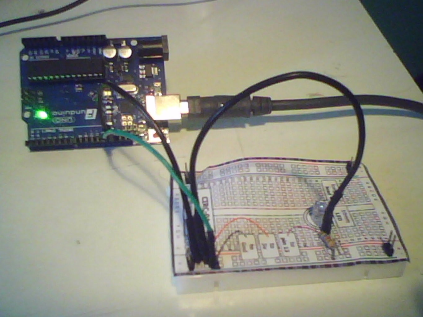
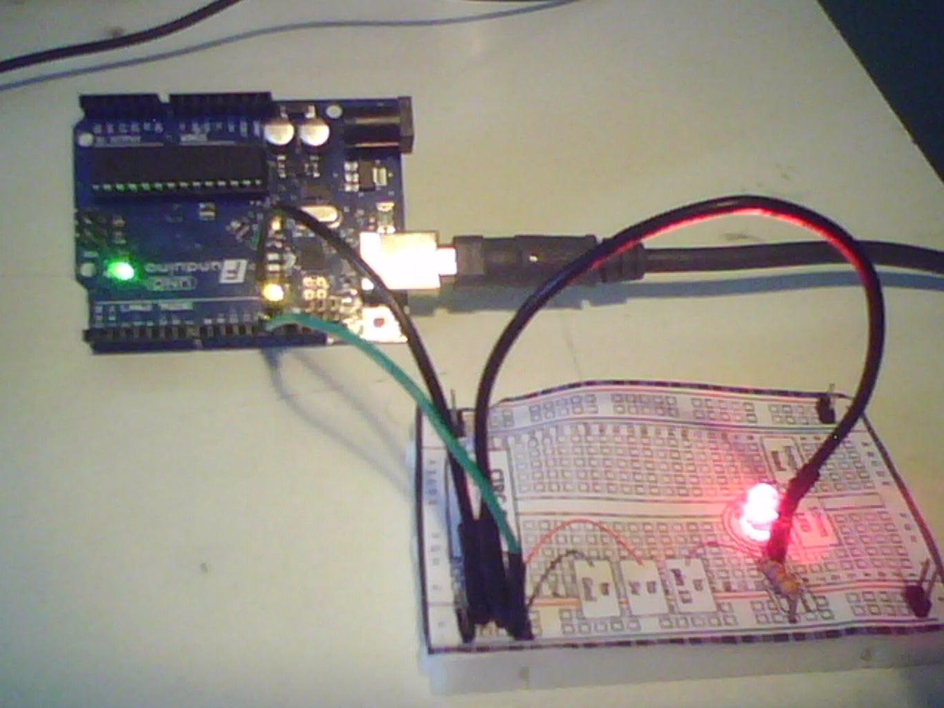
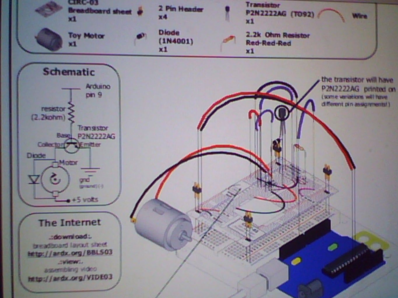
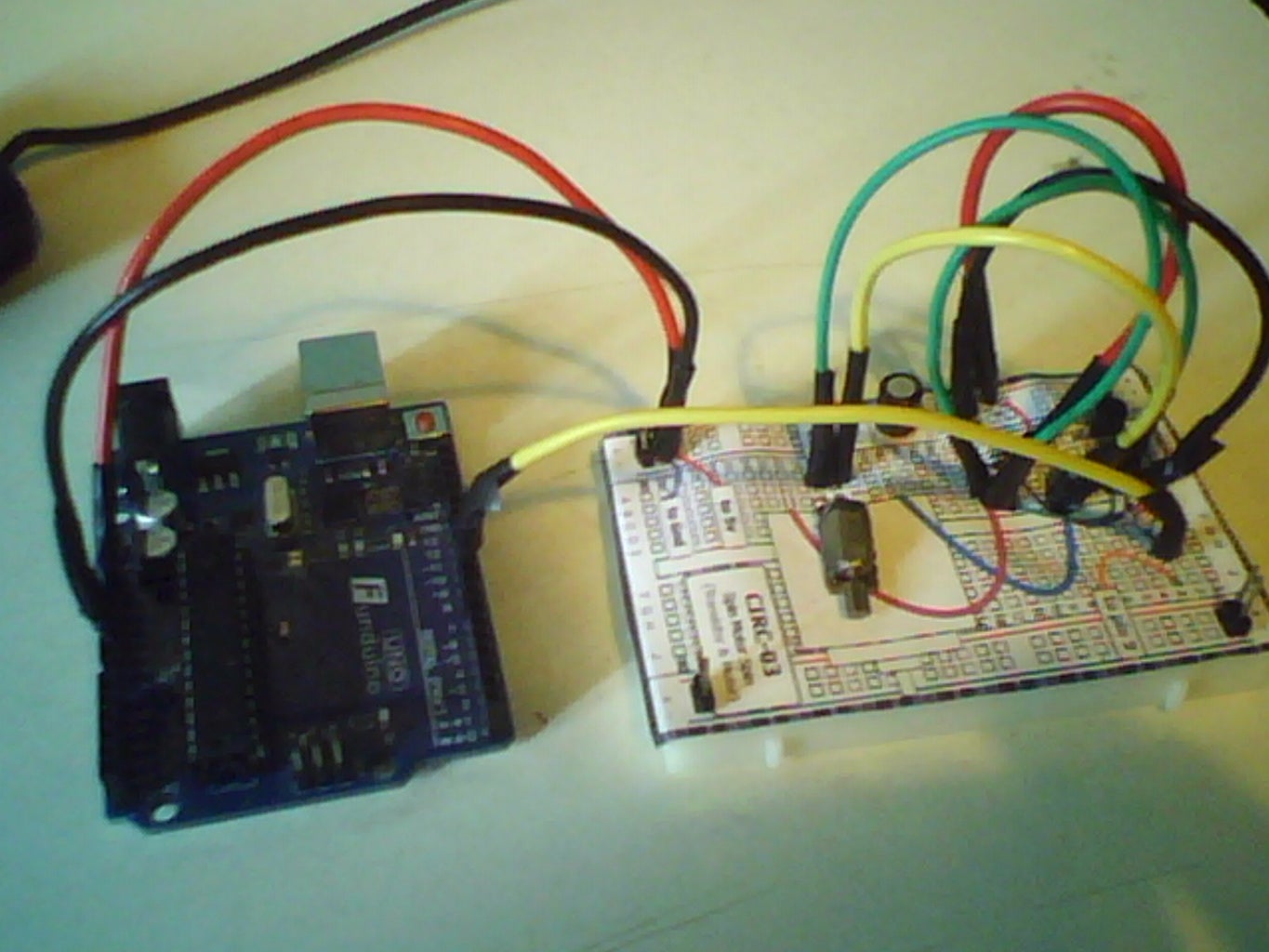
SPIN MOTOR SPIN SKETCH (Covered in several steps) ,Using a ARDX Template to make layout of the circuit more easy when attached to a solderless breadboard,parts required are,lots of jumper wires various colours,Transistor TYPE: (P2N2222A) or a variation of this common transistor type,2.2k resistor to be tied to the base/middle transistor pin,blocking diode feedback stop,so current does not flow back into the micro controller and fry it,or the motor itself,(Optional) 220uf capacitor for if the motor does not spin,and needs the power smoothing out on the way to the motor.
Having done your basic coding in the last Project this will seem much more easy,and more mechanical spinning a motor has many applications from pet toys to robot wheels,same as last time once the circuit has been set up,see pictures and videos,Upload the Code to your IDE Environment CODE After this Line __________________________
int motorPin = 9; // define the pin the motor is connected to
// (if you use pin 9,10,11 or 3you can also control speed)
/* * setup() - this function runs once when you turn your Arduino on * We set the motors pin to be an output (turning the pin high (+5v) or low (ground) (-)) * rather than an input (checking whether a pin is high or low) */ void setup() { pinMode(motorPin, OUTPUT); }
/* * loop() - this function will start after setup finishes and then repeat * we call a function called motorOnThenOff() */
void loop() // run over and over again { motorOnThenOff(); //motorOnThenOffWithSpeed(); //motorAcceleration(); }
/* * motorOnThenOff() - turns motor on then off * (notice this code is identical to the code we used for * the blinking LED) */ void motorOnThenOff(){ int onTime = 2500; //the number of milliseconds for the motor to turn on for int offTime = 1000; //the number of milliseconds for the motor to turn off for digitalWrite(motorPin, HIGH); // turns the motor On delay(onTime); // waits for onTime milliseconds digitalWrite(motorPin, LOW); // turns the motor Off delay(offTime); // waits for offTime milliseconds }
/* * motorOnThenOffWithSpeed() - turns motor on then off but uses speed values as well * (notice this code is identical to the code we used for * the blinking LED) */ void motorOnThenOffWithSpeed(){ int onSpeed = 200; // a number between 0 (stopped) and 255 (full speed) int onTime = 2500; //the number of milliseconds for the motor to turn on for int offSpeed = 50; // a number between 0 (stopped) and 255 (full speed) int offTime = 1000; //the number of milliseconds for the motor to turn off for analogWrite(motorPin, onSpeed); // turns the motor On delay(onTime); // waits for onTime milliseconds analogWrite(motorPin, offSpeed); // turns the motor Off delay(offTime); // waits for offTime milliseconds }
/* * motorAcceleration() - accelerates the motor to full speed then * back down to zero */ void motorAcceleration(){ int delayTime = 50; //milliseconds between each speed step //Accelerates the motor for(int i = 0; i < 256; i++){ //goes through each speed from 0 to 255 analogWrite(motorPin, i); //sets the new speed delay(delayTime); // waits for delayTime milliseconds } //Decelerates the motor for(int i = 255; i >= 0; i--){ //goes through each speed from 255 to 0 analogWrite(motorPin, i); //sets the new speed delay(delayTime); // waits for delayTime milliseconds } }
The above code will allow you to control the the motor being on and off with delay similar to the blink sketch but with a motor,in fact you can use the same coding as the blink sketch to make it spin with delay,just rename LED too Motor Pin to make it easier to understand,then save the sketch as spin motor spin etc,suggested improvements include controlling the speed of the motor with a "Analog" Pin same as the LED Fade sketch,and "Optimizing" the coding to make it smaller,using new functions such as i++ to increase the speed from 0 to 256 analog writes highest setting 5volt output, the "i--" Function does the opposite increments down from 256 to 0 for slowing the motor speed down.. (using this code method is only advisable in large to very large coding programs,such as robotics systems,motor/servo/IR/Data logger coding would leave not much space if any on smaller boards with less memory.
Using Custom Parts can be alot more fun,especially if using a high power vibration motor,using many different kinds of motors to see which works best with this circuit also advisable,small toy motors works best.
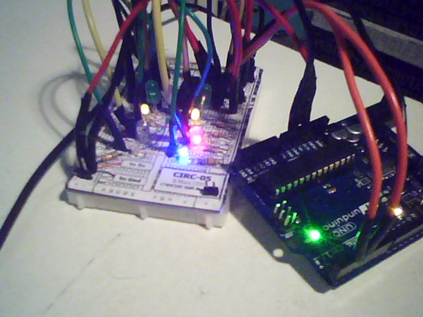
8-BIT SHIFT REGISTER (IC) (Controlling x8 LED's With x3 Pins & LED Animations) In Several Steps....now something more interesting the use of Integrated Circuit tech IC's,the (74HC595 Shift Register) Will do the following,use x3 Arduino Pins to shift out 8-bits of data,allowing LED Animations..for a explanation on how this is done with Data/Latch/Clock Pins on the IC-Chip please look for the microchips Datasheet online ( http://www.nxp.com/documents/data_sheet/74HC_HCT59... ) paste that link into a empty search bar in goggle for the datasheet on this component,get to know it and its workings,and you will understand IC pinouts in no time at all.
Same as always set up your circuit as per the pictures and video shows,also can find online documentation on how to do this in even more detail if needed (Check & Recheck your Wiring here) this will be the most wires you have used yet and it is easy to miss-aline the wires or not push a jumper wire in all the way,making dangerous short circuits if in the power supply area,always check your wiring when doing complex setups such as this,or linking IC chips,as they require alot of wiring,Upload the code Below this line to your IDE save it under whatever name you like in sketch's ___________________________
//Pin Definitions
//Pin Definitions //The 74HC595 uses a serial communication //link which has three pins int data = 2; int clock = 3; int latch = 4;//Used for single LED manipulation int ledState = 0; const int ON = HIGH; const int OFF = LOW;
/* * setup() - this function runs once when you turn your Arduino on * We set the three control pins to outputs */ void setup() { pinMode(data, OUTPUT); pinMode(clock, OUTPUT); pinMode(latch, OUTPUT); }
/* * loop() - this function will start after setup finishes and then repeat * we set which LEDs we want on then call a routine which sends the states to the 74HC595 */ void loop() // run over and over again { int delayTime = 100; //the number of milliseconds to delay between LED updates for(int i = 0; i < 256; i++){ updateLEDs(i); delay(delayTime); } }
/* * updateLEDs() - sends the LED states set in ledStates to the 74HC595 * sequence */ void updateLEDs(int value){ digitalWrite(latch, LOW); //Pulls the chips latch low shiftOut(data, clock, MSBFIRST, value); //Shifts out the 8 bits to the shift register digitalWrite(latch, HIGH); //Pulls the latch high displaying the data }
/* * updateLEDsLong() - sends the LED states set in ledStates to the 74HC595 * sequence. Same as updateLEDs except the shifting out is done in software * so you can see what is happening. */ void updateLEDsLong(int value){ digitalWrite(latch, LOW); //Pulls the chips latch low for(int i = 0; i < 8; i++){ //Will repeat 8 times (once for each bit) int bit = value & B10000000; //We use a "bitmask" to select only the eighth //bit in our number (the one we are addressing this time through value = value << 1; //we move our number up one bit value so next time bit 7 will be //bit 8 and we will do our math on it if(bit == 128){digitalWrite(data, HIGH);} //if bit 8 is set then set our data pin high else{digitalWrite(data, LOW);} //if bit 8 is unset then set the data pin low digitalWrite(clock, HIGH); //the next three lines pulse the clock pin delay(1); digitalWrite(clock, LOW); } digitalWrite(latch, HIGH); //pulls the latch high shifting our data into being displayed }
//These are used in the bitwise math that we use to change individual LEDs //For more details http://en.wikipedia.org/wiki/Bitwise_operation int bits[] = {B00000001, B00000010, B00000100, B00001000, B00010000, B00100000, B01000000, B10000000}; int masks[] = {B11111110, B11111101, B11111011, B11110111, B11101111, B11011111, B10111111, B01111111}; /* * changeLED(int led, int state) - changes an individual LED * LEDs are 0 to 7 and state is either 0 - OFF or 1 - ON */ void changeLED(int led, int state){ ledState = ledState & masks[led]; //clears ledState of the bit we are addressing if(state == ON){ledState = ledState | bits[led];} //if the bit is on we will add it to ledState updateLEDs(ledState); //send the new LED state to the shift register }
This is clearly the Biggest Code yet being more complex then the other so far,dissect the code for yourself this time picking it apart into new functions that are listed,B00000001, B00000010 (Bit codes) 01 being the first 10 being the next so on so forth,try get to know the main 3 parts of the IC chip Latch/Data/Clock pins and where they are located for future projects.
Animations can be downloaded online for the LED's to make them blink in certain ways,try using different colour or Multi-Colour LED's like i did,rather then all the same colour,it makes it more easy to see the animation and looks much better also,make sure all resistors tied to the LED's are inserted correctly,sometimes one will move out of place while you are connecting the mass of jumper wires.
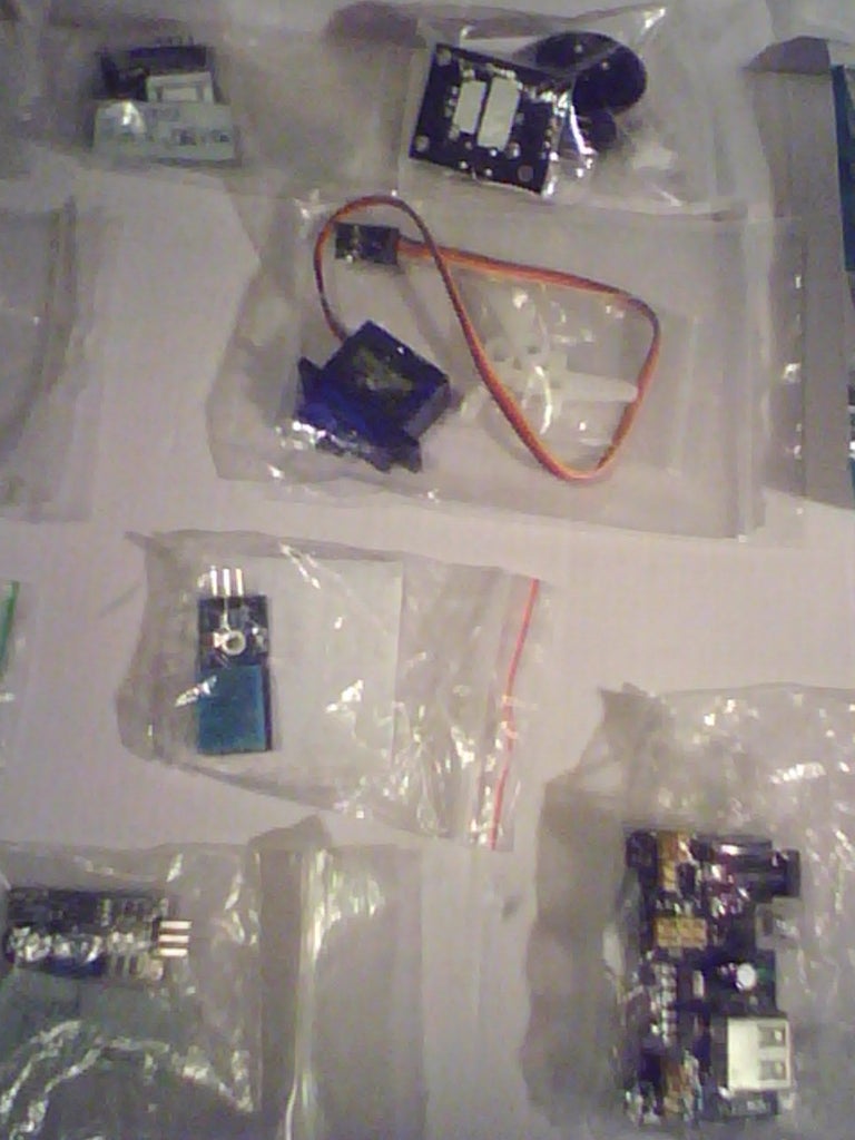
9g SERVO CONTROL (used commonly in robotics) The 9g Mini Servo is somewhat easy to set up movement being timed in pulses check the servos datasheet online for your type of servo,can be used in robotic location systems such as ultrasonic sensor turn ability,door locks,joint movement,and axis servo arms used in factory manufacturing and construction fully automated on pre programmed servo's inside these arms.less steps then usual this time as you by now will know how to set up a circuit and upload programs to your IDE,as well as basic coding functions,and more.
Set up your Servo as per the pictures posted,and add any addition labels for better visual indication of servo angle once done go to the Arduino Main site and search for the servo library yourself learn how to add it by reading up on library's,once done and you have it added to examples or sketchbook,upload the "Sweep" Example that is there must download this in order to use the code below this line___________
#include Servo myservo; // create servo object to control a servo // a maximum of eight servo objects can be created int pos = 0; // variable to store the servo position void setup() { myservo.attach(9); // attaches the servo on pin 9 to the servo object } void loop() { for(pos = 0; pos < 180; pos += 1) // goes from 0 degrees to 180 degrees { // in steps of 1 degree myservo.write(pos); // tell servo to go to position in variable 'pos' delay(15); // waits 15ms for the servo to reach the position } for(pos = 180; pos>=1; pos-=1) // goes from 180 degrees to 0 degrees { myservo.write(pos); // tell servo to go to position in variable 'pos' delay(15); // waits 15ms for the servo to reach the position } }
Play around with the servo for a while,it may get stuck now and then just twist the top back to its starting point and press reset so it restarts the coding library,the servo should then rotate 180degrees and back,try altering the pulse timing in small increments to find one that works better for your servo,next part is pretty easy hook up a 10k Potentiometer to do this attach the pot to analog pin 0 as well as tie it into -/+ connections/rails on the breadboard using jumper wires see my pictures and videos to see how I connected it,or refer to your own expertise,trial and error experimentation is always better,finding it out for yourself,its only 3 wires and 3 for the servo that are already connected,figure the pinout of your pot by yourself its very simple to do you will work it out if you have gotten this far and done all previous experiments.
Attachments
 Arduino Experiments (Supersize Instructable) - Step #3
- Arduino Experiments (Supersize Instructable) - Step #3
- Arduino Experiments (Supersize Instructable) - Step #3
- Arduino Experiments (Supersize Instructable) - Step #3
- Arduino Experiments (Supersize Instructable) - Step #3
- Arduino Experiments (Supersize Instructable) - Step #3
- Arduino Experiments (Supersize Instructable) - Step #3
- Arduino Experiments (Supersize Instructable) - Step #3
- Arduino Experiments (Supersize Instructable) - Step #3
- Arduino Experiments (Supersize Instructable) - Step #3
- Arduino Experiments (Supersize Instructable) - Step #3

Step 4: Skill Level:Basic.(2)


- PIEZO BUZZER (PLAYING TONES&TUNES)
- Simple set-up of the circuit see pictures,here you will be playing a tone melody and song/tune by altering the frequency and pitch of the electric buzzer go to examples on your IDE look at digital and select Tone/Melody and try it out.
- CODE FOR CAN-CAN TUNE BELOW THIS LINE ___________________
int noteFreqArr[] = {
49.4, 52.3, 55.4, 58.7, 62.2, 65.9, 69.9, 74, 78.4, 83.1, 88, 93.2, 98.8, 105, 111, 117, 124, 132, 140, 148, 157, 166, 176, 186, 198, 209, 222, 235, 249, 264, 279, 296, 314, 332, 352, 373, 395, 419, 444, 470, 498, 527, 559, 592, 627, 665, 704, 746, 790, 837, 887, 940, 996, 1050, 1110, 1180, 1250, 1320, 1400, 1490, 1580, 1670, 1770, 1870, 1990, 2100};
long mode = 0;
void setup() { pinMode(4, OUTPUT); // set a pin for buzzer output }
void playNote(long noteInt, long length, long mode, long breath = 25) { length = length - breath; long noteInt2 = noteInt + 12; //1 octave up long noteInt3 = noteInt + 24; //2 octaves up long noteInt4 = noteInt + 36; //3 octaves up long playLoop = length / 100; //divide length by 4, for use in play sequence if(mode == 0) { //mode 0 sequence for (long i=0; i < playLoop; i++){ buzz(4, noteFreqArr[noteInt], 20); delay(5); buzz(4, noteFreqArr[noteInt2], 20); delay(5); buzz(4, noteFreqArr[noteInt3], 20); delay(5); buzz(4, noteFreqArr[noteInt4], 20); delay(5); } } else if(mode == 1) { //mode 1 sequence for (long i=0; i < playLoop; i++){ buzz(4, noteFreqArr[noteInt3], 20); delay(5); buzz(4, noteFreqArr[noteInt4], 20); delay(5); buzz(4, noteFreqArr[noteInt3], 20); delay(5); buzz(4, noteFreqArr[noteInt4], 20); delay(5); } } else if(mode == 2) { //mode 2 sequence for (long i=0; i < playLoop; i++){ buzz(4, noteFreqArr[noteInt3], 20); delay(5); buzz(4, noteFreqArr[noteInt3], 20); delay(5); buzz(4, noteFreqArr[noteInt3], 20); delay(5); buzz(4, noteFreqArr[noteInt2], 20); delay(5); } } else if(mode == 3) { //mode 3 sequence for (long i=0; i < playLoop; i++){ buzz(4, noteFreqArr[noteInt4], 40); delay(5); buzz(4, noteFreqArr[noteInt2], 40); delay(5); } } if(breath > 0) { //take a short pause or 'breath' if specified delay(breath); } }
void loop() { //main course playNote(12, 500, mode); playNote(5, 1000, mode); playNote(7, 250, mode); playNote(10, 250, mode); playNote(9, 250, mode); playNote(7, 250, mode); playNote(12, 500, mode); playNote(12, 500, mode); playNote(12, 250, mode); playNote(14, 250, mode); playNote(9, 250, mode); playNote(10, 250, mode); playNote(7, 500, mode); playNote(7, 500, mode); playNote(7, 250, mode); playNote(10, 250, mode); playNote(9, 250, mode); playNote(7, 250, mode); playNote(5, 250, mode); playNote(17, 250, mode); playNote(16, 250, mode); playNote(14, 250, mode); playNote(12, 250, mode); playNote(10, 250, mode); playNote(9, 250, mode); playNote(7, 250, mode); playNote(5, 1000, mode); playNote(7, 250, mode); playNote(10, 250, mode); playNote(9, 250, mode); playNote(7, 250, mode); playNote(12, 500, mode); playNote(12, 500, mode); playNote(12, 250, mode); playNote(14, 250, mode); playNote(9, 250, mode); playNote(10, 250, mode); playNote(7, 500, mode); playNote(7, 500, mode); playNote(7, 250, mode); playNote(10, 250, mode); playNote(9, 250, mode); playNote(7, 250, mode); playNote(5, 250, mode); playNote(12, 250, mode); playNote(7, 250, mode); playNote(9, 250, mode); playNote(5, 250, mode); delay(250); if(mode == 0) { mode = 1; } else if(mode == 1) { mode = 2; } else if(mode == 2) { mode = 3; } else if(mode == 3) { mode = 0; } }
void buzz(int targetPin, long frequency, long length) { long delayValue = 1000000/frequency/2; // calculate the delay value between transitions //// 1 second's worth of microseconds, divided by the frequency, then split in half since //// there are two phases to each cycle long numCycles = frequency * length/ 1000; // calculate the number of cycles for proper timing //// multiply frequency, which is really cycles per second, by the number of seconds to //// get the total number of cycles to produce for (long i=0; i < numCycles; i++){ // for the calculated length of time... digitalWrite(targetPin,HIGH); // write the buzzer pin high to push out the diaphram delayMicroseconds(delayValue); // wait for the calculated delay value digitalWrite(targetPin,LOW); // write the buzzer pin low to pull back the diaphram delayMicroseconds(delayValue); // wait againf or the calculated delay value } }
- (No need to download any library's for this just copy and paste it to your IDE in an empty sketch and save it as the can-can then upload it and try it out,personally find it very annoying tune when played sure gets one's attention however)
- BUTTON PRESSING (Ability to map buttons for more command & control ability's) .... Button pressing & mapping,firstly single button as an on/off button on when pressed off when released,followed by duel button mapping setting one as an off button and the second an an on button,allowing the creation of a control pad for robot systems,example being a 5button pad up/down/left/right and an action button in the center.
- Follow the pictures and watch the videos to wire up the circuit if you have problems refer to online sources for button mapping with the arduino,always check your wiring before connecting it up and turning on your board then double check as a short circuit can kill your equipment in seconds especially with more High voltage applications...Coding below this line for setting up the buttons _________________________ (FOR SINGLE BUTTON SETUP)_______ /*
Button Turns on and off a light emitting diode(LED) connected to digital pin 13, when pressing a pushbutton attached to pin 2. The circuit: * LED attached from pin 13 to ground * pushbutton attached to pin 2 from +5V * 10K resistor attached to pin 2 from ground * Note: on most Arduinos there is already an LED on the board attached to pin 13. created 2005 by DojoDave modified 30 Aug 2011 by Tom Igoe This example code is in the public domain. http://www.arduino.cc/en/Tutorial/Button *
/ constants won't change. They're used here to // set pin numbers: const int buttonPin = 2; // the number of the pushbutton pin const int ledPin = 13; // the number of the LED pin
// variables will change: int buttonState = 0; // variable for reading the pushbutton status
void setup() { // initialize the LED pin as an output: pinMode(ledPin, OUTPUT); // initialize the pushbutton pin as an input: pinMode(buttonPin, INPUT); }
void loop(){ // read the state of the pushbutton value: buttonState = digitalRead(buttonPin);
// check if the pushbutton is pressed. // if it is, the buttonState is HIGH: if (buttonState == HIGH) { // turn LED on: digitalWrite(ledPin, HIGH); } else { // turn LED off: digitalWrite(ledPin, LOW); } }
(FOR DUEL BUTTON SETUP) ______ int ledPin = 13; // choose the pin for the LED int inputPin1 = 3; // button 1 int inputPin2 = 2; // button 2 void setup() { pinMode(ledPin, OUTPUT); // declare LED as output pinMode(inputPin1, INPUT); // make button 1 an input pinMode(inputPin2, INPUT); // make button 2 an input { void loop(){ if (digitalRead(inputPin1) == LOW) { digitalWrite(ledPin, LOW); // turn LED OFF } else if (digitalRead(inputPin2) == LOW) {
digitalWrite(ledPin, HIGH); // turn LED ON { {
Just copy and past the above with buttons attached to the correct pins,with pull down resistors to make sure the buttons react as on and off,not just on constantly.
(PHOTO RESISTOR SETUP) Some what easy to set up,connect your LED to the correct pin stated in the coding that follows shortly,the photo-resistor needs to be tied into a resistor also see pictures,and is measured by an analog pin 0 unless you set it as another pin,the pin will read the incoming resistor signal and translate it to volts for the LED effectively fading it with the changes in light,i was in a fairly bright room so had to use extreme proximity also there was a crack in the photo resistor that impaired its function even more still however worked enough to demonstrate and teach me how it worked as well as the coding needed to control and measure incoming light intensity..
CODING AFTER THIS LINE _______________________ //PhotoResistor Pin
int lightPin = 0; //the analog pin the photoresistor is //connected to //the photoresistor is not calibrated to any units so //this is simply a raw sensor value (relative light) //LED Pin int ledPin = 9; //the pin the LED is connected to //we are controlling brightness so //we use one of the PWM (pulse width // modulation pins) void setup() { pinMode(ledPin, OUTPUT); //sets the led pin to output } /* * loop() - this function will start after setup * finishes and then repeat */ void loop() { int lightLevel = analogRead(lightPin); //Read the // lightlevel lightLevel = map(lightLevel, 0, 900, 0, 255); //adjust the value 0 to 900 to //span 0 to 255
lightLevel = constrain(lightLevel, 0, 255);//make sure the //value is betwween //0 and 255 analogWrite(ledPin, lightLevel); //write the value }
Sort amount of code not to complicated and using familiar functions such as the analog pins and there mini&max values,,usual deceleration of pins and there modes,new functions include light level constants 0,900,0,255 etc as seen above.
Attachments
- Arduino Experiments (Supersize Instructable) - Step #4
- Arduino Experiments (Supersize Instructable) - Step #4
- Arduino Experiments (Supersize Instructable) - Step #4
- Arduino Experiments (Supersize Instructable) - Step #4
- Arduino Experiments (Supersize Instructable) - Step #4
- Arduino Experiments (Supersize Instructable) - Step #4
Step 5: Skill Level:Intermediate.(1)


- LCD SCREEN SETUP (EXTERNAL SERIAL MONITOR) Many uses for having your own screen automated scrolling messages to warn off people from areas for example,using it as a serial monitor to read outputted data (motion detection) is perfect for this purpose,here basic messages and scrolling the LCD will be learned,alot of wiring is required here as well as a Potentiometer for setting the screen contrast so you can clearly see the message you have pre set into the the microcontroller.
- Connecting up the screen can be somewhat annoying but will get the hang on it after a couple of trys with multiple arduino boards,it will be easy to set up you know how to set up a potentiometer by now having used one to control the servo earlier Use this link for an Arduino instructions set for connection of the screen.
http://arduino.cc/en/Tutorial/LiquidCrystal ,Please Download the Liquid Crystal Library from the site also,it is needed to run the code that enables the LCD screen..by now you know how to extract a zip file and move its content into the examples/sketchbook folder of your IDE location,if you have any problems there is plenty of online content and guides on how to wire up and or link the LCD screen,also a 3 wire shift register interface can be created with the correct tools soldering iron prefboard jumper wires 8-bit shift register,and additional female or male header pins which can be salvaged from an old PC with some de-soldering equipment there are a few instructables on this just search for LCD's and arduino's you will eventually find a couple to show you how to do this as it will save you pins,at the price of more coding,buying a larger board (mega) or using a Prototyping shield with lots of custom welded/soldered extra input pins and power pins,gnd etc.
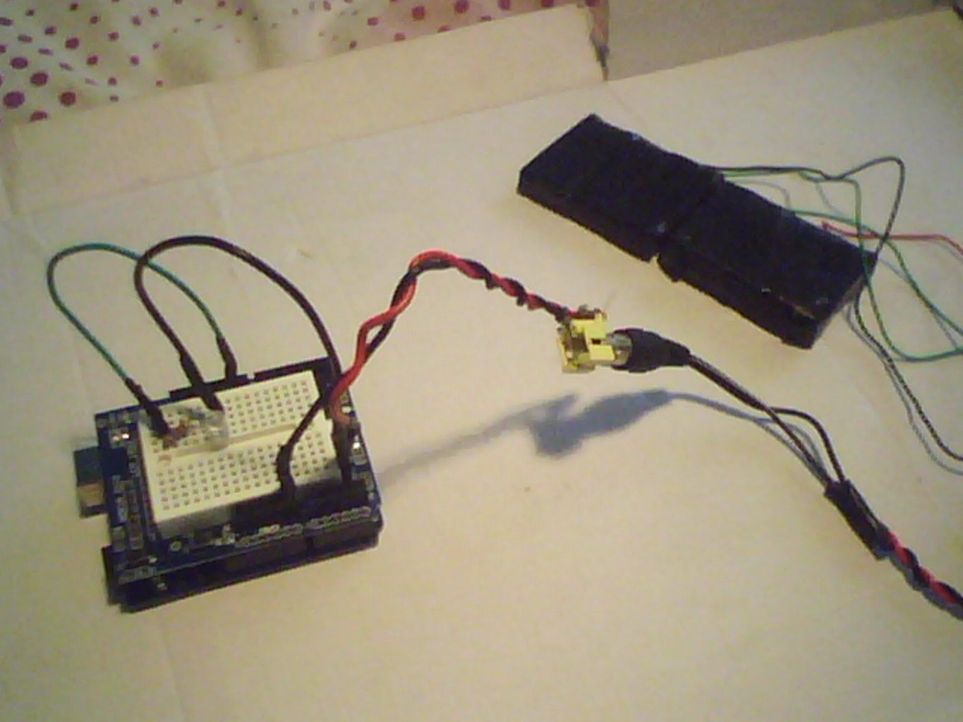
- SOLAR POWER SETUP (Needed for lowering your power consumption and external powering of projects) Use DIY construction panels a few,and recycled old broken solar lights to gain even more for that extra bit of charging power,use high efficiency panels in temporary housing or loose as shown in the pictures,charge up a few batterys 3.3v battery's I use,when connected to an component that requires more linking x2 batterys in series supply's a nice 6.6volts power so only x2 old recycled mobile phone battery's can power a uno for in my experience a total of about 1/2hour's with lower power applications,temperature and external components will increase the load and drain on the stored photonic energy so using a module with a circuit as show ( not advised ) as the extra power the board will take will put a larger drain on the circuit so always use less parts if possible and always use the correct value of resistor in order to not lose or waste your solar power (Being green always advisable where it can be employed and used effectively)
- DHT11 (Temperature & Humidity Sensor) Has many uses making ultrasonic sensors more accurate by comparing air density via measurement of temp/humi,as both effect how the speed of sound is calculated,Data and Environmental Monitoring systems using a "Data Logger" to store all temperature variations,in robotics multiple uses can be employed both of the above for a start,also good for measuring how hot battery's and parts get during use,so you can work out the optimum environment your robot works in most likely work better at lower temperature's as hot components will cool faster,however battery's may supply less power then normal at extremely low temperatures..........Easy to set up only 3 connections 5v & gnd,followed by the signal pin to "Analog 4" as you will be measuring its input value to discern its temp/humidity....No library needed just save the code into a new sketch and name it DHT11,CODE AFTER THIS LINE __________________________________________________________________________________________ /* DHT11 Example Sketch Code for reading the sensor without delay on your program!
Example Code by: Nick Athanasoulas Date: 27/5/2012 FUNCTION: It reads the sensor every 2 seconds without delays. The user can also use the temperature and humidity values directly as an integer and compare it to other values without making new arrays. */ #define DHT11_PIN 4 // ADC0 Define the ANALOG Pin connected to DHT11 Sensor int temp1[3]; //Temp1, temp2, hum1 & hum2 are the final integer values that you are going to use in your program. int temp2[3]; // They update every 2 seconds. int hum1[3]; int hum2[3];
byte read_dht11_dat() { byte i = 0; byte result=0; for(i=0; i< 8; i++){
while(!(PINC & _BV(DHT11_PIN))); // wait for 50us delayMicroseconds(30);
if(PINC & _BV(DHT11_PIN)) result |=(1<<(7-i)); while((PINC & _BV(DHT11_PIN))); // wait '1' finish
} return result; }
long dht11delay_previousMillis = 0; // will store last time LED was updated long dht11delay_interval = 1000; // dht11delay_interval at which to blink (milliseconds)
void setup() { DDRC |= _BV(DHT11_PIN); PORTC |= _BV(DHT11_PIN);
Serial.begin(9600); Serial.println("DHT11 without delay"); Serial.println("Example code by: Nick Athanasoulas"); Serial.println("Ready"); delay(1000); }
void loop() {
unsigned long dht11delay_currentMillis = millis();
if(dht11delay_currentMillis - dht11delay_previousMillis > dht11delay_interval) { // save the last time you blinked the LED dht11delay_previousMillis = dht11delay_currentMillis; byte dht11_dat[5]; byte dht11_in; byte i; // start condition // 1. pull-down i/o pin from 18ms PORTC &= ~_BV(DHT11_PIN); delay(18); PORTC |= _BV(DHT11_PIN); delayMicroseconds(40);
DDRC &= ~_BV(DHT11_PIN); delayMicroseconds(40);
dht11_in = PINC & _BV(DHT11_PIN);
if(dht11_in){ Serial.println("dht11 start condition 1 not met"); return; } delayMicroseconds(80);
dht11_in = PINC & _BV(DHT11_PIN);
if(!dht11_in){ Serial.println("dht11 start condition 2 not met"); return; } delayMicroseconds(80); // now ready for data reception for (i=0; i<5; i++) dht11_dat[i] = read_dht11_dat();
DDRC |= _BV(DHT11_PIN); PORTC |= _BV(DHT11_PIN);
byte dht11_check_sum = dht11_dat[0]+dht11_dat[1]+dht11_dat[2]+dht11_dat[3]; // check check_sum if(dht11_dat[4]!= dht11_check_sum) { Serial.println("DHT11 checksum error"); }
temp1[0]=dht11_dat[2]; temp2[0]=dht11_dat[3]; Serial.print("Temperature: "); Serial.print(temp1[0]); Serial.print("."); Serial.print(temp2[0]); Serial.print(" C"); Serial.print(" "); hum1[0]=dht11_dat[0]; hum2[0]=dht11_dat[1]; Serial.print("Humidity: "); Serial.print(hum1[0]); Serial.print("."); Serial.print(hum2[0]); Serial.println("%");
} } // END OF CODE .
- (ULTRASONIC DISTANCE SENSOR SETUP) Setup the sensor to the correct pins and check your wiring this is an easy setup with advanced applications such as obstacle avoiding robots,distance measuring with ultrasonics for electronic not tape measuring as usual,can be linked with the DHT11 or other temperature sensor to improve accuracy as air pressure effects the speed of sound,and can create errors in the distance calculations..CODING BELOW THIS LINE __________________________________________________________________________________________ /* Ping))) Sensor
This sketch reads a PING))) ultrasonic rangefinder and returns the distance to the closest object in range. To do this, it sends a pulse to the sensor to initiate a reading, then listens for a pulse to return. The length of the returning pulse is proportional to the distance of the object from the sensor. The circuit: * +V connection of the PING))) attached to +5V * GND connection of the PING))) attached to ground * SIG connection of the PING))) attached to digital pin 7
http://www.arduino.cc/en/Tutorial/Ping created 3 Nov 2008 by David A. Mellis modified 30 Aug 2011 by Tom Igoe This example code is in the public domain.
*
/ this constant won't change. It's the pin number // of the sensor's output: const int pingPin = 7;
void setup() { // initialize serial communication: Serial.begin(9600); }
void loop() { // establish variables for duration of the ping, // and the distance result in inches and centimeters: long duration, inches, cm;
// The PING))) is triggered by a HIGH pulse of 2 or more microseconds. // Give a short LOW pulse beforehand to ensure a clean HIGH pulse: pinMode(pingPin, OUTPUT); digitalWrite(pingPin, LOW); delayMicroseconds(2); digitalWrite(pingPin, HIGH); delayMicroseconds(5); digitalWrite(pingPin, LOW);
// The same pin is used to read the signal from the PING))): a HIGH // pulse whose duration is the time (in microseconds) from the sending // of the ping to the reception of its echo off of an object. pinMode(pingPin, INPUT); duration = pulseIn(pingPin, HIGH);
// convert the time into a distance inches = microsecondsToInches(duration); cm = microsecondsToCentimeters(duration); Serial.print(inches); Serial.print("in, "); Serial.print(cm); Serial.print("cm"); Serial.println(); delay(100); }
long microsecondsToInches(long microseconds) { // According to Parallax's datasheet for the PING))), there are // 73.746 microseconds per inch (i.e. sound travels at 1130 feet per // second). This gives the distance travelled by the ping, outbound // and return, so we divide by 2 to get the distance of the obstacle. // See: http://www.parallax.com/dl/docs/prod/acc/28015-PI... return microseconds / 74 / 2; }
long microsecondsToCentimeters(long microseconds) { // The speed of sound is 340 m/s or 29 microseconds per centimeter. // The ping travels out and back, so to find the distance of the // object we take half of the distance travelled. return microseconds / 29 / 2; }
Open the serial monitor once you upload the code and put your hand in front of the sensor moving it back and forth watching as the distance changes to test it works accurately,remember air pressure can effect it temperature&humidity and other environmental factors.(ONLY VIDEO AVAILABLE UNTIL I REPEAT IT AS NEVER TOOK PICTURES)
Step 6: Skill Level:Intermediate.(2)


- (ADAFRUIT SD CARD DATA LOGGER MODULE) A Large module designed with saving your arduino's pin's in mind as SD cards use as many pins as an LCD screen leaving not many usable pins,Comes with RTC (Real Time Clock) attached and built in with 6+year lifespan,clock must be programmed once in order to save the current time via your PC's internet timing,please sync the clock on your PC if possible and has that option on your internet clock,will explain how to do all this shortly.. First off get yourself an SD/HC Card with which to log data on,and format it into fat 16/32 format via an external formatter,windows is not strictly designed to do this as with stand alone programs so search a SD card formatter online... (My SD card looks that way due to it was glued with a layer of epoxy followed by painted camo pattern to give it a more military data logger look came out nicely)
- Setting up the SD card reading ability library's will be needed if you have a different SD Logger please look up its datasheet online and use the pinout settings and library required for your module.
http://arduino.cc/en/Reference/SD (Use this link and download the SD card library) once you have that upload the Card Info Sketch in your IDE with the library added in your IDE location examples/sketchbook and see if it initializes the card,sometimes you may have a bad card that is cheaply made and it will not read,only way to get around this is get another one that works,so test your card if possible before you bother with checking if the logger reads it in the first place,make a few notepad files inside an empty card otherwise no files will show on a freshly formatted card,next setting up the RTC Clock built into the module for data logging on the SD card with dates & times of recorded data,allowing graph plotting for environmental or robotics data,movement is an environmental aspect as is temperature and humidity,robotics aspect being motor speeds battery & part optimum temperature as well as servo angle's or other mechanical systems that you want to record for optimization or checking performance of parts....RTC Clock Needs a Library installed into the IDE. https://learn.adafruit.com/ds1307-real-time-clock-... Additional Link just in case. https://learn.adafruit.com/ds1307-real-time-clock-... Once installed upload the code search how to call up the function now() in order to get the current RTC chip time shown on the serial monitor on the Arduino IDE or alternatively read the second link and all its relevant information.........once done you have completed setting up the module for logging data.. (go into that at a future point as I have only recently got this module and not yet used it myself,will post videos and pictures along with how it was done in detail with any relevant links I have.
- (ARDUINO MOTION SENSOR,WITH AUDIO & VISUAL ALERT) Low level Security System with audio & visual detection,can be outputted to a serial monitor if wished and will show motion detected when detected,IR detection sensor needed along with a Piezo electric buzzer & long wire LED light,Solderless breadboard recommended but not necessary,upon moving in range of the sensor about 15 to 20ft in my experiences with indoor testing,could be connected to a servo with the right coding library's could fire off a trigger to a defensive device strobe,banner,nerfgun etc,upon detection of movement making this an automated defence setup medium level security,camera systems being simple low level no ability to defend itself unlike this strategically placed system which has that ability,only place in places where you know no one apart from you should be,example being inside your PC,screwing around with hard drives etc,or inside a whole room if it has only one door,and no windows. CODING BELOW THIS LINE _____________________________________________________________________________ int ledPin = 13; // choose the pin for the LED int inputPin = 2; // choose the input pin (for PIR sensor) int pirState = LOW; // we start, assuming no motion detected int val = 0; // variable for reading the pin status int pinSpeaker = 10; //Set up a speaker on a PWM pin (digital 9, 10, or 11)
void setup() { pinMode(ledPin, OUTPUT); // declare LED as output pinMode(inputPin, INPUT); // declare sensor as input pinMode(pinSpeaker, OUTPUT); Serial.begin(9600); }
void loop(){ val = digitalRead(inputPin); // read input value if (val == HIGH) { // check if the input is HIGH digitalWrite(ledPin, HIGH); // turn LED ON playTone(300, 160); delay(150);
if (pirState == LOW) { // we have just turned on Serial.println("Motion detected!"); // We only want to print on the output change, not state pirState = HIGH; } } else { digitalWrite(ledPin, LOW); // turn LED OFF playTone(0, 0); delay(300); if (pirState == HIGH){ // we have just turned of Serial.println("Motion ended!"); // We only want to print on the output change, not state pirState = LOW; } } } // duration in mSecs, frequency in hertz void playTone(long duration, int freq) { duration *= 1000; int period = (1.0 / freq) * 1000000; long elapsed_time = 0; while (elapsed_time < duration) { digitalWrite(pinSpeaker,HIGH); delayMicroseconds(period / 2); digitalWrite(pinSpeaker, LOW); delayMicroseconds(period / 2); elapsed_time += (period); } }

Step 7: Skill Level:Intermediate.(3)


- (Home-brew Build your own arduino) (Several pdf's on building your own arduino below for your own reference and save you looking for yourself)
Building your own Arduino with all the components needed,most can be recycled to cut down on costs,soldering to a pref-board section with lots of spare parts it is possible to make your own Arduino with a unique setup pin configuration and or ability's or custom modules from which to attach to your own arduino design,setting up the basic arduino is easy and requires a few,gather all the parts you need to make it,solderless breadboard,Atmega328 Micro-controller chip,Multiple Colours of LED,Jumper Wires alot,16k mhz Crystal oscillator,22pf Capacitors for the timing crystal,5volt regulator,Pin Inputs,Printout from above or online,selection of resistors at different ratings 560ohm & 10k ohm,100uf Capacitors x2,A Couple of 22nf capacitors,and a tactile push-button..all can be recycled apart from the ATmega chip unless you're very lucky in scavenging,make the power supply,chip & timing with crystal,capacitors for smoothing timing and voltages,resetbutton for the chip,and resistors tied into each LED light..
Once you have built your own Arduino you can cut down on costs of getting additional boards and make your kit a whole lot more portable even pocketsize,also increases your electronics knowledge with microcontrollers and how they function,with every part working in tandem to achieve its purpose. (See pictures and Video)
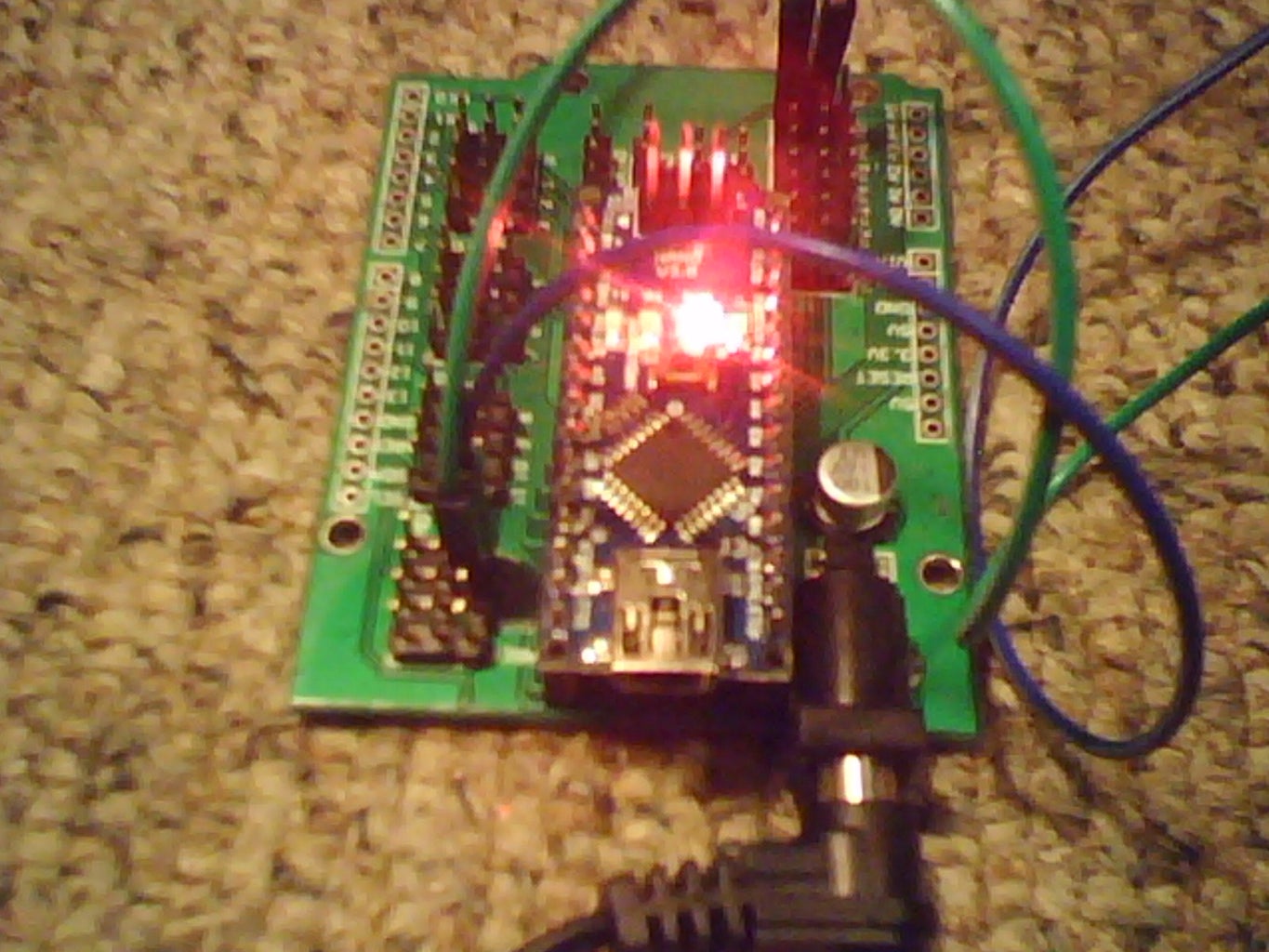
- (Arduino Micro Board) Lower power requirements than previous boards you have used perfect for solar power,however needs a Serial to USB programmer,as there is no chip for that on the board,small profile size and diameter but retains the same programming memory as a nano but even smaller,powering it off a small 3.3volt button battery it lights up like a Christmas tree. (used in smaller projects and robotics this kind of board maybe necessary to cut down on power usage and weight along with space,that is why I added this here as microbot's will need micro microcontrollers.
- (Arduino Nano Board With Module) Small profile Arduino Nano with serial to usb chip built in so no need for a programmer just a usb micro cable to connect up to your PC & IDE software,yet again smaller power requirements then an uno board making this another good choice for solar powered micro controllers,as well as micro robotics projects where low profile low weight boards can be used effectively,using this with the Arduino Blue/Green Module will turn it into a full Uno like board with DC jack input and lots of extra connection pins,however they require Female to female header cables to link to sensors and other equipment,added this board as it is somewhere in between the full uno and the mini micro along with building your own arduino,and as such will be a common board to use also cheap in price but not as cheap as a micro without serial to usb chip built in.
Step 8: Skill Level:Intermediate.(4)


(Wireless Commands and equipment section) (Remote controlling)
- (RF 315/433 MHz Transmitter-receiver setup) Using the Virtual wire library's downloaded online,go for the older version if you are having trouble using the most recent update for the modules can download the most recent version here http://www.seeedstudio.com/depot/images/product/Vi... as for the older version you will have to hunt that down yourself with goggle if you have trouble or it might be one of the below links somewhere in there with the coding of the RF Kit. Below will be a selection of links to help you set up this circuit,once mastered many remote control ability become available to you......links follow ____
- 315/433 MHzRF REFERENCE LINKS. 1: http://www.jamesrobertson.eu/pages/2013/feb/24/rf-... 2: http://ninjablocks.com/blogs/how-to/7501042-adding... 3: http://www.pjrc.com/teensy/td_libs_VirtualWire.htm... 4: http://www.wes.id.au/2013/07/decoding-and-sending-... 5:http://bayesianadventures.wordpress.com/2013/09/20/arduino-rf-communications-data-encoder-for-virtualwire/
Step 9: Skill Level:Advanced.(1)


(CUTTING COSTS)
- Saving power and money can be made easy with recycling skills get used to piling up old radios,tv's,pc's,and electronic scrap in a out of the way cupboard or under the stairs,in the shed where ever you have space to spare,taking them apart and de soldering all the parts you deem usable inside,many many parts can be scavenged saving possible 100s in bulk orders of the same parts from factory's or spending cash in your local electronics store,In arduino projects this means more funds for addition high performance parts and extra modules in the money you saved from recycling parts you never had to buy otherwise,such as packs of capacitors & resistors in various ratings,Customised parts are another big way to save yourself buying addition parts such as solderless breadboards which can be improvised with old PC IDE cables,SMD parts can be recycled with a bit of soldering skill,and give you low profile low power smd profile parts with which to use in your projects,additional tools (drill) can be improvized for spares,make your own power cables for custom recycled battery packs with which to power your arduino's externally off grid,try get hauls of parts not just one or two but 30 to 60 + to make it worthwhile and make a saving in components,use a multimeter to test each part that can be tested LEDs also need testing save you finding that unlucky dead one just when you needed it,label and organize all your capacitors and resistors,in fact all your parts especially if tested and working label them as such in zip lock bags for safety of the components inside and protection from moisture in the air,solar charging battery's is a good idea as will lower power consumption of your experiments while giving you a temporary off grid powering ability for your microcontrollers and electronics,DIY panels advised and recycled if possible to yet again save even more money better spend on high performance parts for your robotics projects,security devices,drones flyers,mini tanks,combat bots and other machines that require reliable and usually somewhat expensive singular parts and modules ranging from anything to £1 to £10k for a single part that will do everything you tell it too,these devices are usually hard to set up and assume you have studied how before having it in your hands so research things you buy before you buy them and shop around for the exact same item but cheaper using search engines to help you,and compare sites if able and necessary..
Step 10: Skill Level:Advanced.(2)

(Can be used to add additional projects of yours adapting this instructable for your own projects you deem complicated enough to claim difficulty)
Step 11: Skill Level (Master) (For Them Extra Special Creations)

(For them extra special creations that will be very rare,and have awesome capability's and or generally awesome such as combat robots,drone systems,life saving tech etc)
Step 12: Robotics With Arduino. (Skill Level:Intermediate to Advanced)

(Empty)
(For your own use or my future updates if any)
Step 13: Idea's.

(IDEAS AREA)
Any cool idea's I come up with,Or that others think should be added here,I will add your idea's however small,it will likely be of use to someone,somewhere creating a new project,especially custom components or part idea's that also have the added benefit of saving funds.
1.Low level arduino Security system,using a pre programmed code and sound/visual indication systems,linked to a long and far away serial monitor LCD screen showing when motion has been detected,also audio alert will be heard and likely freak out the person that triggered it.. (low level security)
2.Medium level arduino Security system,using a pre programmed servo and IR sensor/s,a custom weapons module box,containing the following servo aimed devices,taser,mini rocket,coil-gun,mini spiky flyer bot,crossbow&projectile,nerf dart fired with air pressure valve setup,and any other ideas for a small weapons box module for automated home defences,make sure to put up plenty of large warning signs outside the house,so any thief etc had there warning before trying to enter a protected house (linking the setup to an external power unit solar battery's will negate turning it off by simply destroying a fuse box in the basement.
3.("hazzalandy"Suggested) A CNC lathe using a motor shield.. (any links found on this will be added here) https://www.instructables.com/id/3-Axis-Arduino-Bas...
Step 14: Q&A

(Questions and assistance area)
Wiring is your enemy always check then double check your wiring,and placement of all components before saying something does not work,also debugging each part testing if it works with a multimeter can be effective,and you may have a single none functional part more likely if recycled parts so test them repeatedly just to be sure it works.
Power is a problem and will be in all advanced projects and robotics,as battery's are heavy and sometimes heat up alot making unstable power output as does cold temperature decrease battery efficiency,recycle old mobile phone battery's of the same type,as they are lightweight compare to large D-cells that are heavy and likely to drain faster than say a Li-Poly mobile phone battery pack of custom linked in series battery's equals out with about 6+ volts for x2 compare to a D-cells 1.5v output,as well as being likely less heavy and lower profile compare to standard battery's.
(Arduino's require a certain amount of power in order to work,if your circuit "Lags" or seems to have Limited RF Range it is most likely due to the battery's falling below the required power levels to power both board & project,robots are very power greedy,try find out the power usage of every part,in order to optimize operation times)
1.Circuit/experiment not working (Check all parts,power input,and wiring repeatedly,if still no joy,take it apart and start from scratch/beginning of the experiment)
2.Problems with the Code.(check your on the right COM port,and have the right Board selected,this is a common mistake forgetting the simple things,if missing a part of the code,debug it for yourself and try to type in the missing function part usually { missing from ending of a function,if a larger part is absent post online and ask for help,there are some wizards in coding out there that will be able to see your problem instantly even in larger coding systems,asking around instructables or commenting on arduino projects for help also advisable)

Participated in the
Battery Powered Contest

Participated in the
Gadget Hacking and Accessories Contest

Participated in the
Sensors Contest


