

Introduction: Arduino Light Theremin


A theremin is a electronic music device that can sense the position of a performers hands and create musical sounds all without the performer ever touching the device. For our light theremin we are going to adapt this concept and create a theremin that controls color instead of music.
Things you will need:
- Arduino
- Computer
- LED's
- Photoresistor
- Resistors
- Wax/Diffusion Paper
- Hot Glue
- Tape
Step 1: Wire Up LED's
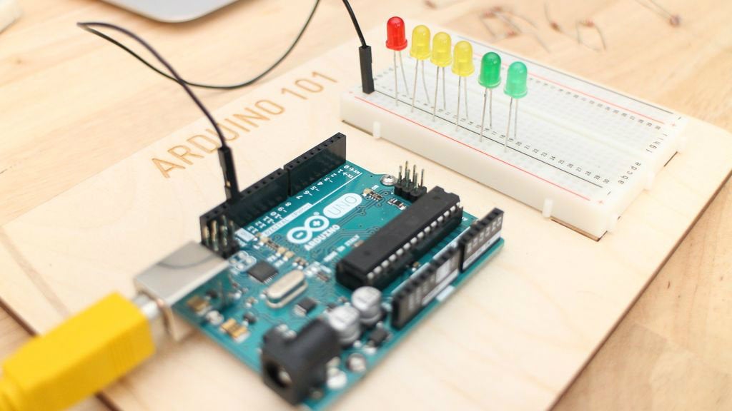
Lets begin by grabbing 6 LED's out of our kit. I chose 2 green, 3 yellow and 1 red. You can add more if you'd like, just make sure you add an extra resistor and wire to an open Arduino pin. Keep in mind that the Arduino can not supply a lot of power, so at a certain point adding more LED's just makes them all dimmer.
Ground Wire / Add LED's
Start by adding a wire between the ground (negative "-" ) rail of the breadboard and the GND pin of the Arduino. This makes sure that all the components on the Arduino and breadboard now share a common ground and can make a complete circuit. Next, plug the short leg (ground) of the LED into the ground (negative) rail of the breadboard
Add Resistors & Wires
Your going to need 6 resistors, I've chosen to use the 220 Ohm (red, red, brown), because the LED's will be bright enough to see but not draw to much power from the Arduino.
Step 2: Photoresistor Circuit

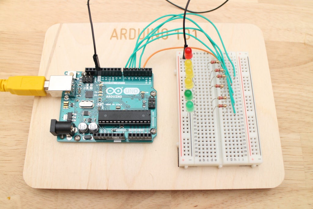
To make the photoresistor circuit we are again going to create a voltage divider. Grab your photoresistor and a 10K Ohm resistor (Brown, Black, Orange). Place one leg of the photoresistor into the ground rail of the breadboard and the other leg in any row of the breadboard.
Next add a wire from the 5V output on the Arudino to a different row on your bread board and have the 10K Ohm resistor bridge the 5V power row and photoresistor row.

Finally, now that we have made a voltage divider we need to get the signal from the divider to the Arduino, so take another wire and plug one end into the photoresistor and 10K resistor row and the other end into A0 (analog pin 0) on the Arduino.
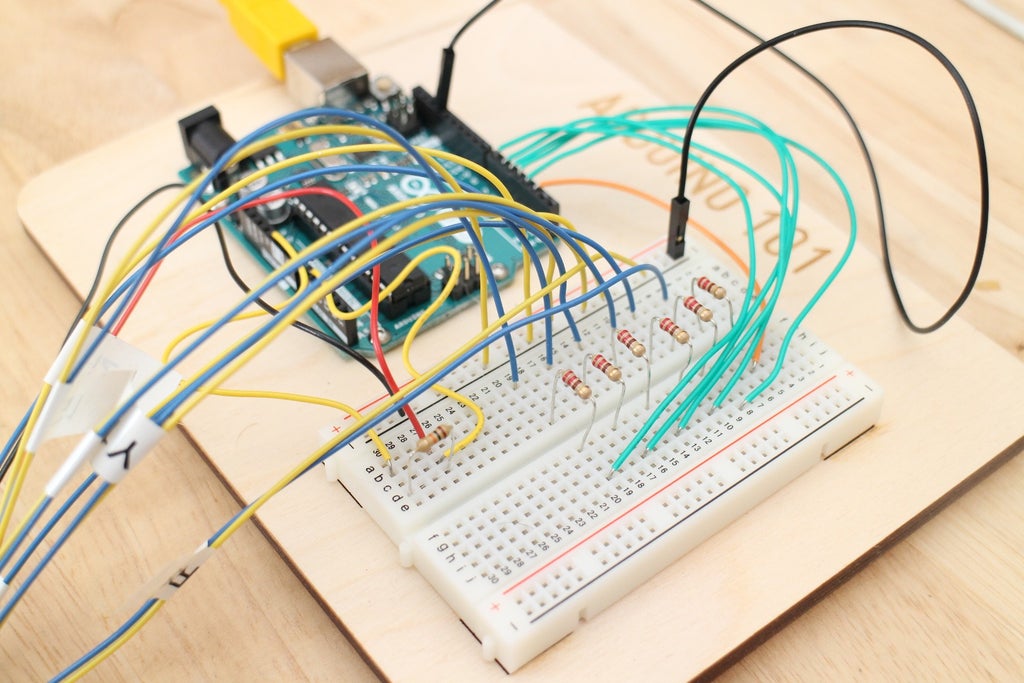
Your circuit should now look similar to the one above.
Step 3: Coding Part 1
To code the light theremin we are going to expand on the previous analog sensor lesson, and take it a step further by having one sensor trigger multiple LED actions. First, download the attached LightTheremin.ino and open it up in the Arduino IDE. To begin we need to initialize all 6 LED's. I kept the naming conventions fairly standard here, but you can label the LED's according to any convention you prefer.
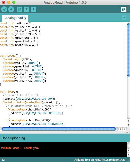
const int redPin = 2 ;
const int yellowPin1 = 3 ;
const int yellowPin2 = 4 ;
const int yellowPin3 = 5 ;
const int greenPin1 = 6 ;
const int greenPin2 = 7 ;
const int photoPin = A0 ;
Now that each LED is named we need to setup our inputs and outputs:
void setup() {<br>  Serial.begin(9600);
  pinMode(redPin, OUTPUT);
  pinMode(greenPin1, OUTPUT);
  pinMode(greenPin2, OUTPUT);
  pinMode(yellowPin1, OUTPUT);
  pinMode(yellowPin2, OUTPUT);
  pinMode(yellowPin3, OUTPUT);
}
Note that we are also starting a serial port connection so we can calibrate the device later on. The 9600 value is the speed at which the computer and Arduino talk to each other. This is called Baud Rate, and you can read more about it in the additional resources section.
Attachments

Step 4: Coding Part 2
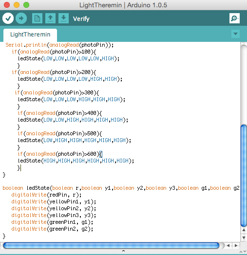
Building off our analog sensor code, we are going to utilize the same LED function but we need to expand on it a little bit to be able to accommodate for the larger amount of LED's. To do this we want to increase the number of function parameters and make sure we trigger the extra pins.
boolean ledState(boolean r,boolean y1,boolean y2,boolean y3,boolean g1,boolean g2){	     digitalWrite(redPin, r);
    digitalWrite(yellowPin1, y1);
    digitalWrite(yellowPin2, y2);
    digitalWrite(yellowPin3, y3);
    digitalWrite(greenPin1, g1);
    digitalWrite(greenPin2, g2);
 }
In this ledState function we have parameters r, y1, y2, y3, g1, and g2. Setting these to either HIGH or LOW in the main loop with turn on or off these LED's.
Step 5: Coding Part 3
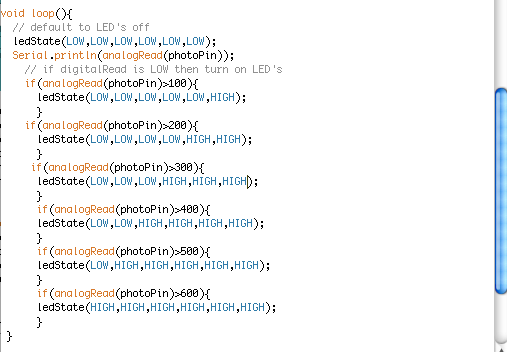
Lets get to the real meat of this code and dive into the main loop. We know we want different LED's to light up in accordance with the distance away your hand is from the sensor. This means that more LEDs should light up when less light is hitting the sensor (as your hand covers it up). As we saw in previous lessons the ADC value of the photoresistor circuit increases with a decrease in light, so we want to structure our code in a way light lights up more LED's as the ADC value increases.
Whew, that was a brain bender! Lets take a look at the code to help us understand what we need:
void loop(){<br>  // default to LED's off
  ledState(LOW,LOW,LOW,LOW,LOW,LOW);
  Serial.println(analogRead(photoPin));
    if(analogRead(photoPin)>100){
      ledState(LOW,LOW,LOW,LOW,LOW,HIGH);
      }
    if(analogRead(photoPin)>200){
      ledState(LOW,LOW,LOW,LOW,HIGH,HIGH);
      }
     if(analogRead(photoPin)>300){
      ledState(LOW,LOW,LOW,HIGH,HIGH,HIGH);
      }
      if(analogRead(photoPin)>400){
      ledState(LOW,LOW,HIGH,HIGH,HIGH,HIGH);
      }
      if(analogRead(photoPin)>500){
      ledState(LOW,HIGH,HIGH,HIGH,HIGH,HIGH);
      }
      if(analogRead(photoPin)>600){
      ledState(HIGH,HIGH,HIGH,HIGH,HIGH,HIGH);
      }
 }
Ahhhh, now this makes more sense. We are constantly checking the value of the photoPin and then light up more and more LED's the higher that value gets. As you'll see in the video on the next step, these default values worked pretty well for me with the ambient light in the room, but you may have to play around with these values somewhat to get them reacting to the distance of your hand in the way you want.
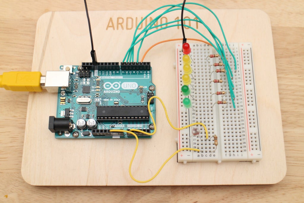
Step 6: Bread Board Test
Lets upload the code to the Arduino and play with our new Theremin.
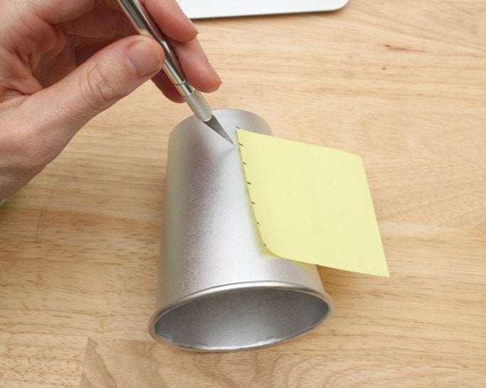
Step 7: Making Theremin Enclosure

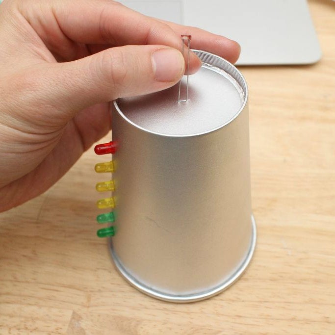
The main body of the theremin is a household paper cup. I spray painted it silver to give it a retro-future vibe. I then proceeded to cut 6 slits, spaced 1/2" apart, with an hobby knife. Then I test fit the LED's.
Finally cut a slit in the top of the cup and feed through the photoresistor
Step 8: Theremin Wiring Part 1
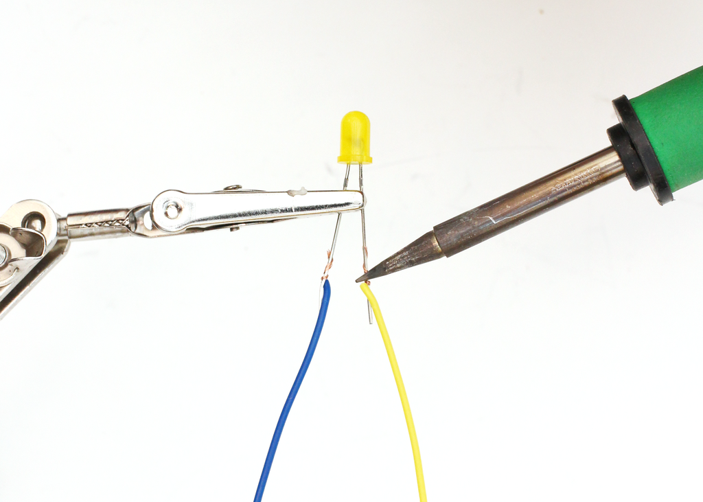
Begin by cutting enough wire to cover the positive and negative leads of all 6 LED's and the photoresistor. I used yellow and blue for the negative and positive leads of the LED's. Next, solder these on to the LED's and if you want extra style points you could add come some heat shrink tubing.
Because we are dealing with so many wires I highly recommend labeling each pair of wires so rewiring your breadboard will be much easier. By the time you finish you will have a whole mess of wires coming out of the back end of your theremin. I decided to keep everything neat and tidy by hot gluing them down to each other and then to the theremin.

Step 9: Theremin Wiring Part 2

Now its time to plug back in the LED's. The yellow wires (GND) go into the ground bus on the breadboard, and the blue wires go into the same row as their respective resistor.
This process should be relatively straight forward. When you are finished upload the code we developed earlier and get ready to use your awesome new light theremin.
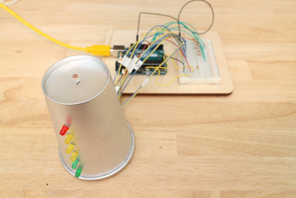
Step 10: Light Theremin
Now that it's all wired up lets try out our new Light Theremin :)


