

Introduction: Arduino Max7219 Led Matrix Display Tutorial


Hi guys in this instructables we will learn how to use led matrix display with max7219 display driver with Arduino to display animation and text on this led Matrix display.
Step 1: Things You Need


For this instructables we will need following things :
Arduino uno
Led Matrix display with max7219
Jumper wires
Breadboard
Step 2: Connections
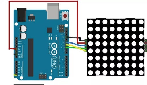
Before we go into all this we need to connect everything together according to the shown schmatics in the image.
Step 3: Coding Part
you need to download and install in your Arduino IDE the LedControl library. To install the library follow these steps:
Click here to download the LedControl library :
https://github.com/wayoda/LedControl/archive/maste...
You should have a .zip folder in your Downloads
Unzip the .zip folder and you should get LedControl-master folder
Rename your folder from LedControl-master to LedControl
Move the LedControl folder to your Arduino IDE installation libraries folder
Finally, re-open your Arduino IDE
Using the LedControl library functions
The easiest way to display something on the dot matrix is by using the functions setLed(), setRow() or setColumn(). These functions allow you to control one single led, one row or one column at a time.
Here’s the parameters for each function:
setLed(addr, row, col, state)
addr is the address of your matrix, for example, if you have just 1 matrix, the int addr will be zero.
row is the row where the led is located
col is the column where the led is located
state
It’s true or 1 if you want to turn the led on
It’s false or 0 if you want to switch it off
setRow(addr, row, value)
setCol(addr, column, value)
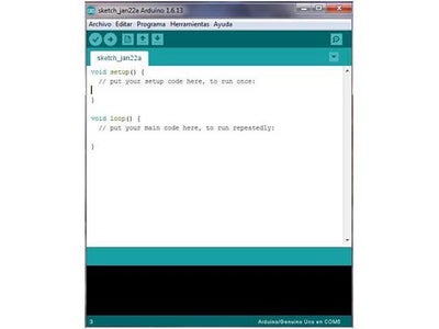
Copy the following code & Upload it to your arduino board :
#include "LedControl.h"
#include "binary.h"
/*
DIN connects to pin 12
CLK connects to pin 11
CS connects to pin 10
*/
LedControl lc=LedControl(12,11,10,1);
// delay time between faces
unsigned long delaytime=1000;
// happy face
byte hf[8]= {B00111100,B01000010,B10100101,B10000001,B10100101,B10011001,B01000010,B00111100};
// neutral face
byte nf[8]={B00111100, B01000010,B10100101,B10000001,B10111101,B10000001,B01000010,B00111100};
// sad face
byte sf[8]= {B00111100,B01000010,B10100101,B10000001,B10011001,B10100101,B01000010,B00111100};
void setup() {
lc.shutdown(0,false);
// Set brightness to a medium value
lc.setIntensity(0,8);
// Clear the display
lc.clearDisplay(0);
}
void drawFaces(){
// Display sad face
lc.setRow(0,0,sf[0]);
lc.setRow(0,1,sf[1]);
lc.setRow(0,2,sf[2]);
lc.setRow(0,3,sf[3]);
lc.setRow(0,4,sf[4]);
lc.setRow(0,5,sf[5]);
lc.setRow(0,6,sf[6]);
lc.setRow(0,7,sf[7]);
delay(delaytime);
// Display neutral face
lc.setRow(0,0,nf[0]);
lc.setRow(0,1,nf[1]);
lc.setRow(0,2,nf[2]);
lc.setRow(0,3,nf[3]);
lc.setRow(0,4,nf[4]);
lc.setRow(0,5,nf[5]);
lc.setRow(0,6,nf[6]);
lc.setRow(0,7,nf[7]);
delay(delaytime);
// Display happy face
lc.setRow(0,0,hf[0]);
lc.setRow(0,1,hf[1]);
lc.setRow(0,2,hf[2]);
lc.setRow(0,3,hf[3]);
lc.setRow(0,4,hf[4]);
lc.setRow(0,5,hf[5]);
lc.setRow(0,6,hf[6]);
lc.setRow(0,7,hf[7]);
delay(delaytime);
}
void loop(){
drawFaces();
}
Step 4: Output

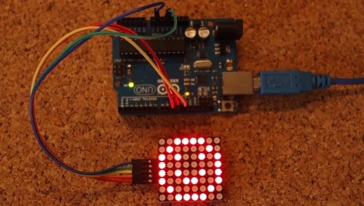
After connecting everything together and uploading the code to arduino you'll able to see the smiley animation as my display shown in image.


![Tim's Mechanical Spider Leg [LU9685-20CU]](https://content.instructables.com/FFB/5R4I/LVKZ6G6R/FFB5R4ILVKZ6G6R.png?auto=webp&crop=1.2%3A1&frame=1&width=306)


