

Introduction: Arduino Robots
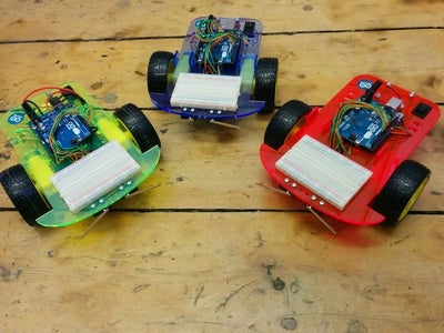


These are my take on a small re-programmable robot using an Arduino as the brains.
These were built as part of my work as Maker in Residence at Derby Silk Mill in the UK.
I wanted to integrate something physical with the Code Club that is being run at the Silk Mill museum. I also wanted to have something that could be altered, changed and upgraded using the tools within the Silk Mill.
This is a simple plastic base with two motorised wheels and a motor driver which is controlled by an Arduino. There are two sensor switches on the front, which could be changed for, maybe, an ultrasonic sensor.
There is an area of breadboard for adding additional circuitry.
There is more information about my residency here and about the other Makers in Residence here.
Step 1: Parts and Tools Required

The parts you will nedd are:
- 1 x A4 sheet 3mm perspex/acrylic
- 2 x right angled geared motor
- 2 x Wheels to fit
- 1 x Motor driver board
- 1 x Arduino Uno
- 1 x Breadboard
- 1 x 25mm swivel caster wheel
- 2 x long lever microswitches
- 1 x 6 x AA battery holder
- 1 x On/Off switch DPST
- 4 x 12mm hex threaded spacers
- 8 x 6mm hex threaded spacers
- Various M3 fixings, machine screws and nuts
- 1 x 2.1mm barrell jack plug - to fit Arduino input power socket.
- Wire
Tools you will need are:
- Soldering iron and solder
- Drill with countersink bit.
- Access to a Laser cutter
Step 2: Laser Cut the Base Plate


Cut out the attached .dxf or .svg file in the 3mm acrylic using your handy laser cutter (or one at a loacl hackspace). Maybe come down to the Silk Mill to use their laser cutter?
You will have 5 pieces - the main base and four identical motor holders.
You might need to alter the switch hole for your exact switch shape.

Step 3: Add PCB Stand-offs


We dont want some of the screws to stick out, so I used counter sunk head screws and a countersinking drill bit to ensure the screw heads are flat.
The screws that are under the breadboard and under the battery holder all need to be countersunk.
This means countersinking two lots of four holes and adding spacers to attach the Arduino and to attach the motor driver. The Arduino will sit on the top of the board, so the countersunk holes are on the bottom.
The motor driver is on the base of the unit, so the countersunk holes are on the top.
Screw on 6mm or 10mm threaded hex spacers using short countersunk M3 machine screws, as shown.
Step 4: Add Battery Holder


Add the 6 x AA battery holder to the underside of the base using 2 x M3 machine screws.
Step 5: Add Motors to Base


Solder 15cm wires to each of the motors.
Attach the motors using the plastic motor holders. One of these fits through the slot and the other has a notch to stop it sliding down.
The machine screws which hold the motor need to be 28mm long. This is difficult to find so I used 30mm screws and cut them down slightly. Using the 30mm screws meant they hit into the battery pack.
Do this on both sides and tighten to hold the motor.
These pictures show this being done after the battery holder has been added - this is not ideal as the holder gets in the way of the nuts. Next time I would put the motors on first then attach the bvattery holder.
Step 6: Add Bump Sensors


Add the two microswitch sensors on to the front of the unit.
There are mounting holes for both smaller and larger standard microswitches.
I used two smaller microswitches with 37mm levers. The levers are not quite long enough and I will add a longer piece to them in the future.
I used M2.5 machine screws and nuts, as the holes were too small for M3.
Step 7: Add Power Switch


The power switch pushes through the hole at the back of the base.
I used a single pole switch in this version and switched everything in the negative line - this is not ideal and I should have use a douple pole single throw switch to switch both the motor power supply and the Arduino power supply.
Two power supplies are required as the motors only need 3 or 4.5V, where as the Arduino input needs to be 6-12V.
I sorted this by tapping the 6 x AA battery holder at the mid point, so there is a supply of 3 x AA batteries (4.5V) and 6 x AA batteries (9V). This will mean that half the batteries will run down more quickly, but they can be rotated.
Step 8: Add Back Caster Wheel


The two motors can be driven to stee the robot.
The back swivel caster spins depending on the direction the robot is travelling.
I wanted the robot base to be level, so used some spacers to make the caster wheel a bit lower.
Iused 4 x 12mm M3 PCB spacers for this, but layers of acrylic could be used for this.
Ensure the heads of the screws do not interfere with the caster wheel spinning around.
Step 9: Add Motor Driver


The motor driver screws on to the underneath of the base of the unit.
4 x short M3 machine screws are used, so it can be removed in the future.
The output pins of the arduino cannot supply enough current to run the motors (you could damage your Arduino ifd you wire these motors directly).
The motor driver has four inputs to control two motors in two different directions. This motor driver can control up to 2A peak current.
Step 10: Add Wheels


The wheels just push fit onto the geared motors.
Step 11: Add Arduino Uno


The Arduino Uno fits onto the top of the robot. Use 4 x short M3 machine screws to hold it onto the spacers we attached.
Step 12: Wiring Diagram

We are going to wire up the robot accroding to the attached wiring diagram.
Five Arduino outputs are used to control the motor:
- Motor driver Sleep - controls if the motor driver is on or off
- Motor 1 forwards
- Motor 1 backwards
- Motor 2 forwards
- Motor 2 backwards
There are two digital inputs:
- Left microcswitch sensor
- Right microswitch sensor
There are two power supplies - one at 4.5V and one at 9V.
(Note: I used a Kitronik motor driver, rather than the poloulou one shown in the diagram.)
Step 13: Wire Motor Driver


We solder the wires from the two motors to the outputs of the motor driver.
Use the vaious holes in the base so wires are kept neat and contained.
There are 7 wires to attach to the motor driver inputs:
- +4.5V power
- Ground
- Sleep
- Motor 1 forwards
- Motor 1 backwards
- Motor 2 forwards
- Motor 2 backwards
The ground wire will be connected to the common ground from the AA battery pack.
The +4.5V wire comes from a tap in the middle of the 6 x AA battery pack.
This goes through one pole of the On/Off switch.
Step 14: Add Power Wiring


Add a wire to the middle of the 6 x AA battery pack, as shown.
I looped the wire around the metal spring and soldered it, but being careful not to melt the battery holder plastic too much.
I extended the red wire from the 6 x AA battery holder and took this through the other pole of the power switch and to the Arduino power input.
I used a 2.1mm barrel jack to power the Arduino - this means we can easily unplug it and replace the Arduino, if required.
Wire the +ve wire to the inner pin and the ground to the outer of the barrell plug. Remember to put the cover on before you solder....
We now have power to everything.
Step 15: Finish Motor Controller


The wires form the motor controller are wired to inputs on the Arduino.
These can be changed in software, but I cohose the following:
- D8 - Motor 1 forwards
- D9 - Motor 1 backwards
- D10 - Motor 2 forwards
- D11 - Motor 2 backwards
- D12 - Sleep
I soldered these wires on to header pins which I plugged into the socket on the Arduino.
Step 16: Wire Bump Sensors


The microswitches connect to ground whne activated.
I used a ground wire which goes to the common pin of the two microswitches.
Two other wires god back to digital inputs on the Arduino - I used D6 and D7, but this can be changed in software.
Step 17: Add Breadboard


The breadboard is for future changes and is stuck onto the top of the front of the robot.
A commonly available ultrasonic distance sensor can easily be added to give thre robot more sense.
Step 18: Program Arduino

I wrote a very simple Arduino sketch, given here.
This is a 'bump and go' sketch which makes the robot back away and then turn slightly when one of the front sensors are activated.
You need to upload this using a USB cable via the Arduino IDE.
Step 19: Add Batteries and Let It Run!


These robots have been designed to be highly configurable and reporgrammable.
The plan is to use program them using Scratch and a converter which converts the Scratch code into and Arduino sketch.
I will try and add instructions for doing this when I can.
I produced four of these simple robots for the Silk Mill code club - hopefully they will be programmed to do amazing things by our next generation of skilled coders....


