

Introduction: Arduino Rocket Data Logger


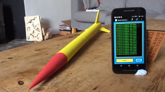


This instructable will show you how to make a model rocket with a data logger payload.The data logger uses an Arduino Pro Mini and a GY-86 IMU (Inertial Measurement Unit - typically used in quad copters) to record altitude, temp, pressure and g force. The data is stored on an SD card and also broadcast via a Bluetooth module. The live data can be seen on your Android smart phone using an app called Talking Serial Monitor . This helps validate the code is working when the electronics are mounted in the rocket before launch. A small alarm has been built in to help you find the rocket if it gets lost! You can either build your own rocket or use a rocket kit. The data logger weighs 35 grams and will fit rockets with an inside diameter of 30mm or larger.
Building a rocket is fairly straight forward, requiring only basic tools. The data logger is a little more involved and may require some fiddly soldering (depending on your approach).
Disclaimer: The data gathered is approximate allowing you to visualise the rockets trajectory and see how high it actually went as well as the acceleration events and average speeds. More detailed info on model rocket physics may be found here.
Rocketry can be dangerous, make sure children are supervised and you launch in a remote area. Check the air laws concerning small rockets before launching in your area!
Parts:
Logger
- GY-86 IMU
- Arduino Pro Mini (5v, 16Mhz) ( an Arduino Nano would also work)
- HC-06 Bluetooth Module
- Nano-tech 120mAh 2S 25C 7.4V Lipo Battery (or other small battery would work)
- Micro SD card module and card ( for each flight expect to need roughly 600KB of space)
- Jumper wires
- Piezo buzzer
- Breadboard
- JST connectors
Rocket:
- Estes BT55 Body Tube
- Estes NC-55 Nose Cone
- Estes BT 55 Body Tube Coupler
- Estes D Engine Mount Kit
- Estes D12-7 Motors
- 5mm Balsa sheet
- 5mm foam board
- Launch pad
- Electric igniter.
- Parachute
- Elastic cord
- Recovery wadding
Tools
- Hobby knife
- FTDI - USB adapter
- Glue gun
- Wood glue
- Soldering iron
- Acrylic paint
Step 1: Rocket Design + Build


Design
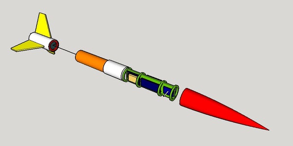
You may want to start by sketching the design of the rocket on paper or do a mock up model in Sketchup to check the data logger will fit.
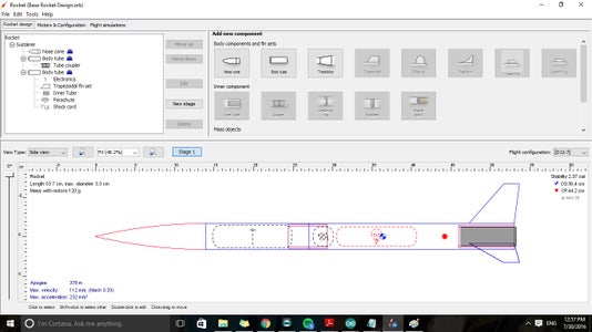
You can optimise your design by downloading a free program called Open Rocket. This allows you to simulate your rocket design with different motors, body sizes, fin and nose cone shapes as well as payload weights. I have attached my open rocket design to get you started.
Build
If you use Estes components as I did the actual build is relatively simple.
- Start by making the motor mount as detailed in the Estes instructions.
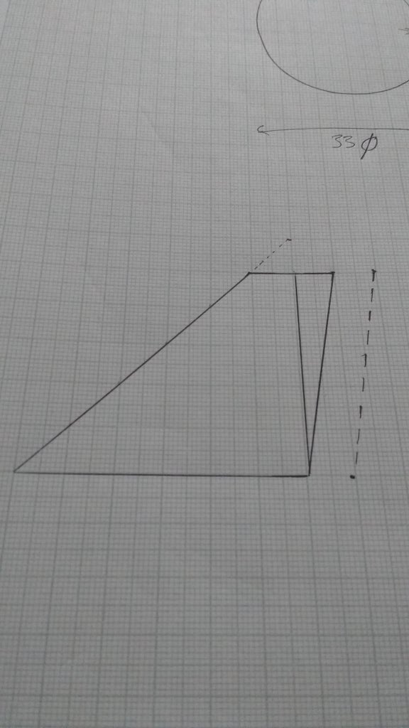
- Draw out your fin shape on paper, cut this out and transfer the outline to the balsa sheet.
- Cut the fins out using the hobby knife.
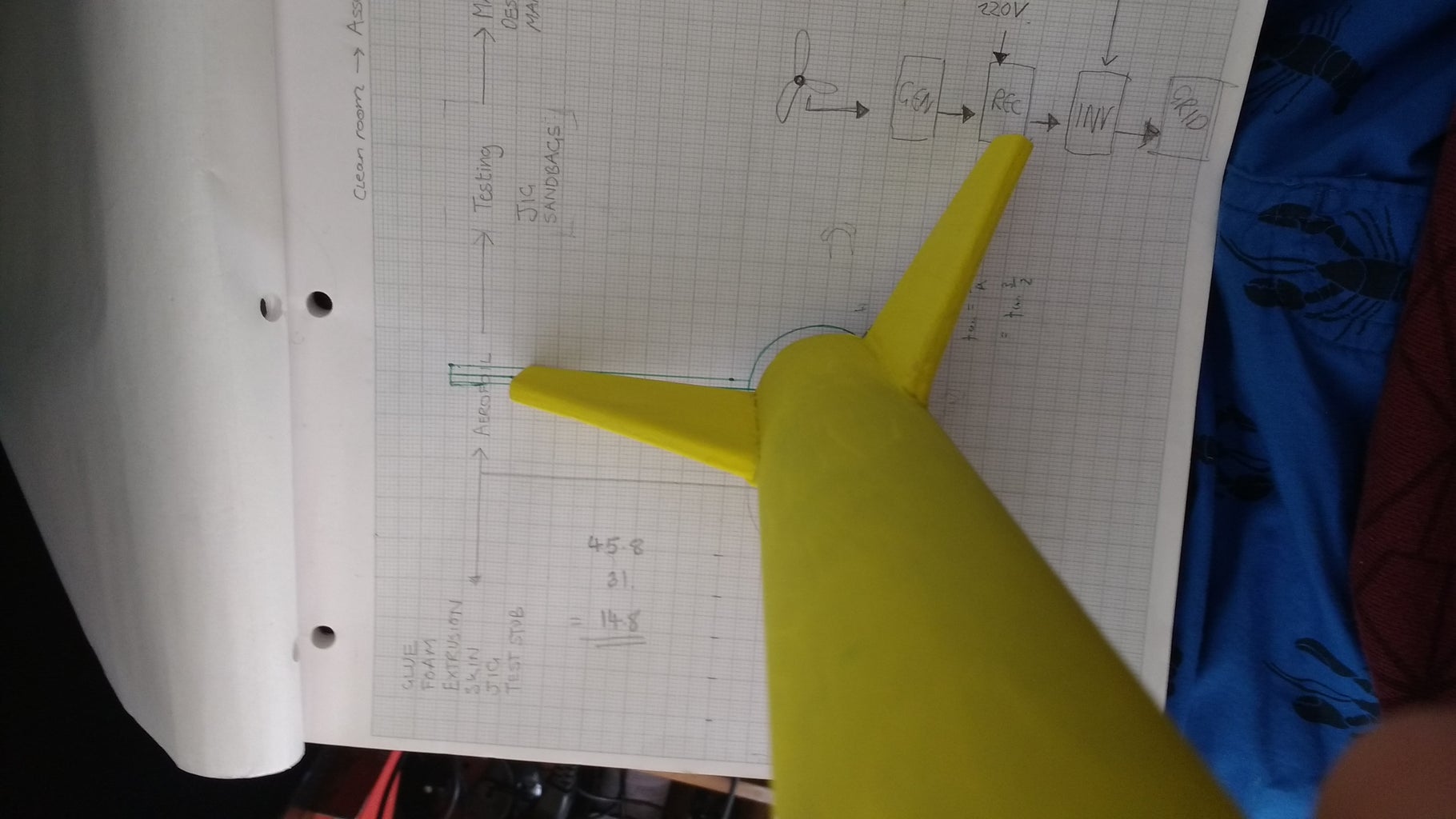
- Draw a circle on a piece of paper the same diameter as the body tube with lines at 120 degrees. Place the end of the body tube on the circle and align the fins using the guide. Use some glue to attach the fins.
- Cut the body tube and glue in the body coupler. This is the part that will separate when the rocket deploys the parachute. The lower portion will contain the motor and parachute. The upper portion contains the data logger and nose cone.
- Attach a shock cord between the two sections.
- Install a parachute, these can be made from a plastic bag or bought from Estes.
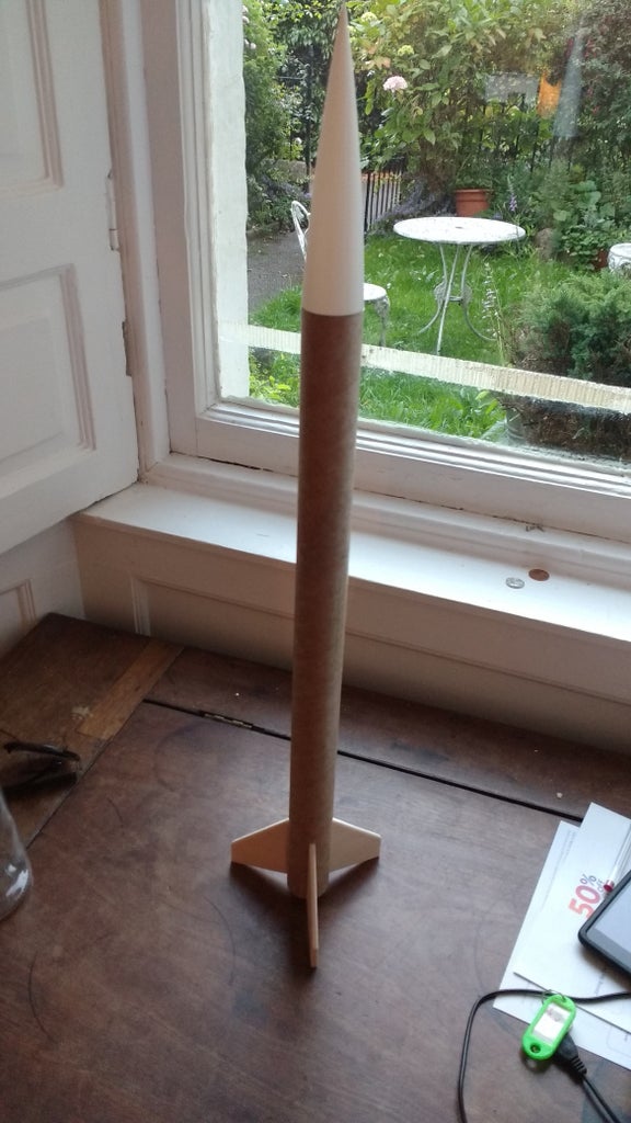
- Decorate the rocket as you like.
Attachments

Step 2: Wiring Diagram

Wiring
Its best to build the circuit on a breadboard to test and refine the code to suit you before hard wiring things together. I used an arduino uno to test the components then hard wired an arduino mini. The pinouts are the same for both boards.
SD CARD:
- 5V
- GND
- CS - PIN 4
- SCK - PIN13
- MOSI - PIN 11
- MISO - PIN 12
GY-86
- 5V
- GND
- SCL - PIN A5
- SDA - PIN A4
- INTA - PIN 2
BLUETOOTH
- 5V
- GND
- TX - RX
- RX - TX
BATTERY
- The balance connector that comes with the battery was replaced with a JST connector.
Once your happy with the logger you can solder the components together for a secure connection (see step 4).
Step 3: Data Logger Code

How it Works
The code operates by taking the data from the GY-86 and making a string that it prints to the SD card. The GY-86 has a 3 axis accelerometer, gyroscope and magnetometer built in as well as a barometric pressure sensor. It uses 3 chips, an MPU6050, HMC883L and an MS5611 to do this. For simplicity the code only uses the accelerometer readings in one orientation and the barometric data (i.e it only measures accel readings in the vertical orientation). If you want to carry out more complex analysis of the data you may want to add more data to the string by modifying the code.
Installation
Install the following libraries by going to Sketch > Import Library...>Add Library...
- wire (should be included in the arduino IDE)
- SPI (should be included in the arduino IDE)
- SD (should be included in the arduino IDE)
- MPU6050 - the file attached has been modified to allow the sensor to sense up to +-16G.
- I2Cdev
- MS5611
Upload the code to the arduino once the libraries are installed.
You should see a string being printed to the serial monitor like this
287.08,21.07,97924,2112,145031
This string is split like this
- First number = absolute altitude in meters
- Second = temperature (this may over read initially, it should stabilise if left to run)
- Third = pressure in pascals
- Fourth = raw acceleration reading (divide by 2048 to get value in G)
- Fifth = time in milliseconds since the code started running.
Test the acceleration reading is correct by holding the sensor in the X direction, the value should read around 2000. Dividing this number by 2048 will give you a "G" reading of around 1 which is 1 G which is 9.81m·s−2
You should be able to see a change in temp by holding the sensor. You should see a change in altitude by lifting the sensor up or down. The buzzer will only work if the SD card is inserted. I have indicated in the code what numbers to change to alter the buzzer time delay and tone. The buzzer isn't terribly loud but will help you locate the rocket in long grass etc.
Bluetooth
Connection via an Android phone is straight forward using the Talking Serial Monitor app. Make sure your phones Bluetooth is on, turn on the arduino and click connect on the app. It may ask for a password which is probably 1234 or 0000. Once connected a solid blue light will light up on the Bluetooth module. The data that would normally be seen on the serial monitor will now be shown on the screen. This feature was included so that you can check the arduino is working correctly before launching.
Step 4: Building the Holder and Hard Wiring


Holder
- The holder was built from 5mm foamboard and can be modified to suit your rocket dimensions.
- It is simply two disks that fit snugly inside the body tube with a flat piece connecting them.
- Cut key ways in the disks and flat piece so that they fit together then secure them with hot glue.
- Cut a small slot to allow wires to be routed from one side to another.
- When mounting the electronics use a small piece of foam board to act as a standoff then glue the circuit to that.
Hard Wiring
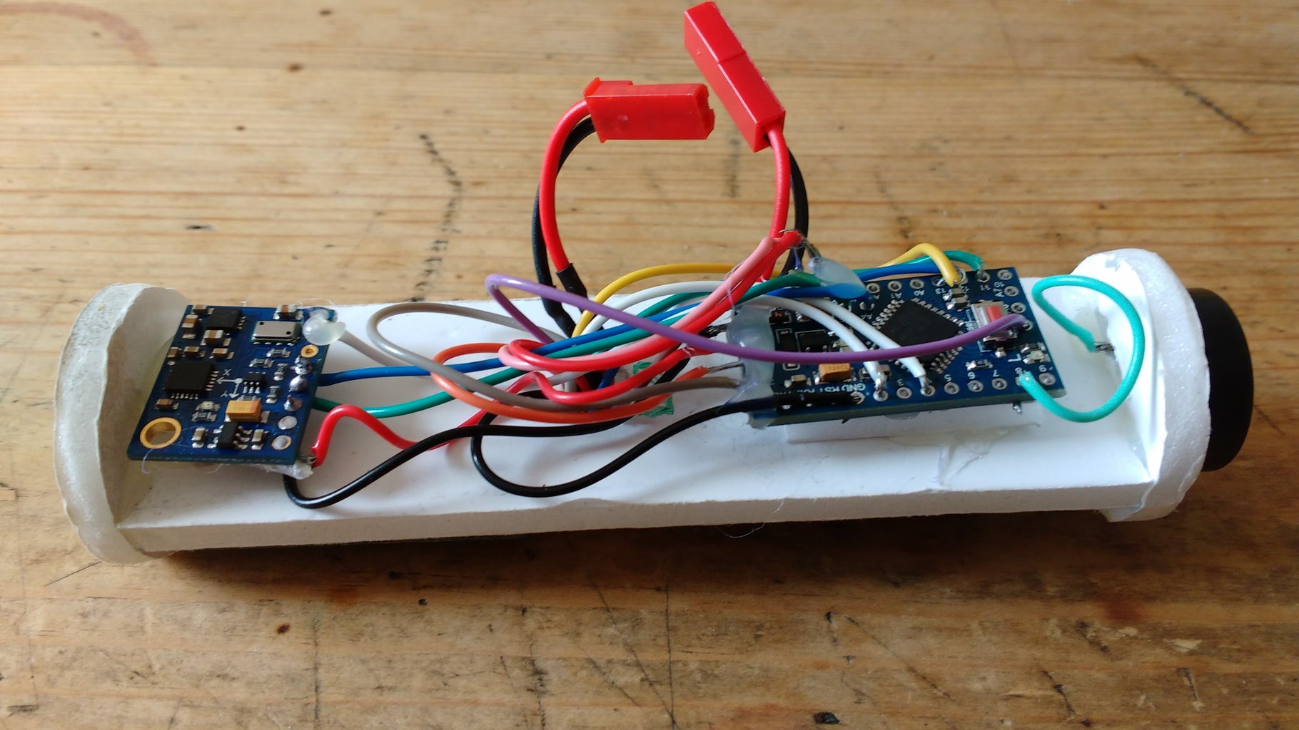
- It is important to mount the GY-86 correctly, mount it in the x direction ( x arrow pointing up towards the nose of the rocket).
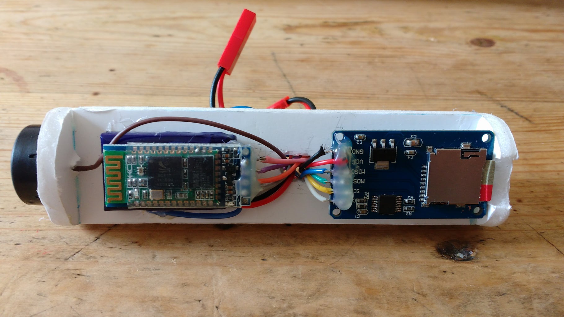
- If you hard wire your components the logger will be more compact and robust enough to withstand the forces associated with rocketry.
- Hot glue can be used to make sure the connections are extra secure.
- This job was fiddly, you could use short jumper wires here if you prefer not to solder, this will be a little more bulky and the connections less secure.
- The Bluetooth module was glued on top of the battery to save space.
- When mounting the SD card reader make sure there is space to allow the card to be inserted and removed. I had to cut a small slot in one of the end disks to allow for this.
Step 5: Launch and Data Processing


Before launching the rocket use the app to ensure the logger is working. Attach some tape round the nose cone to prevent it coming off during the parachute deployment. Launch the rocket in an open area!
Once you have completed your flights its time to get the data from the SD card. There will be a .txt file on your SD card. Open it on your computer and copy the data into excel or google sheets. Use the format (text to columns) option to split up the data. Plot the data as you like, more information on model rocket physics can be found here:
https://www.grc.nasa.gov/WWW/k-12/VirtualAero/BottleRocket/airplane/shortr.html
You can now experiment with different rocket shapes and sizes, compare your data with Open Rockets predictions or work out approximate speeds and accelerations of your flight. Happy rocketeering!

Second Prize in the
Space Contest 2016


