

Introduction: Arduino Tachometer


I had a lot of unused modules i ordered from ebay laying around , felt like i need to make something with them.For next few projects i will be playing with motors and reducers so i insted of buying tachometer for 15+ bucks i decided to design and create one myself.Code,STL files and more info about this project can be found on its github page.
Step 1: About This Project

This is open source tachometer project that is focused on making small ,compact and precise tachometerThere are 2 design versions that use same code but housings are slightly different.More about thoese different designs can be found on github because here only one version will be shown and built.
It works by mesuring time between 2 impulses caused by reflective tape on rotating object.After it mesures time, it uses it to calculate RPM and display it on OLED display, really simple .
To use this tachometer you will need to have some kind of reflective tape( I used aluminium foil) that will cover about 1-1.5 cm of the shaft that will be rotating.Rest of the shaft can be any other colour , but i recommend to make rest of the rotating object black because you will have much less trouble calibrating.
Step 2: Gather All Parts!


Parts needed:
1.Arduino pro mini Link
2.IR sensor Link
3. I2C OLED display 128x64 Link
4.5v Boost converter Link
5.Li ion battery charger Link
6.18650 Li-Ion battery(got them from laptop battery)
7.Slide switch Link
8(OPTIONAL)SMD push button Link
9.(OPTIONAL) magnetic wire Link
10. 15mm M3 screws Link
11. M3 nuts Link
12. M2 5mm screws
13.FTDI USB to TTL Serial Adapter Link
Also you will need some wires to connect everything .
Step 3: 3D Print All Needed Parts


i printed everything with my prusa i3 mk2s , with 0.2 mm layer hight. Print top and bottom cover upright with supports.


Step 4: Soldering Pins to Screen

You will need to solder 4 pins of the screen like shown on the picture. Try to get 45 deegres angle but precision is not crucial because you can bend them later.
Step 5: Attach Screen to Top Plate

Attach screen to top cover with 4 (or 2 if there is too much pressure) M2 5mm screws. board with buttons is optional . I myself placed it there even tho i didnt connect any buttons .But in the future you can then add some additional options if you decide to place button board.
Step 6: Screen Cover

Attach screen cover with 2 M2 5mm screws. There are 2 versions of screen cover , one with holes for buttons and one with none.
Step 7: Assembly 1

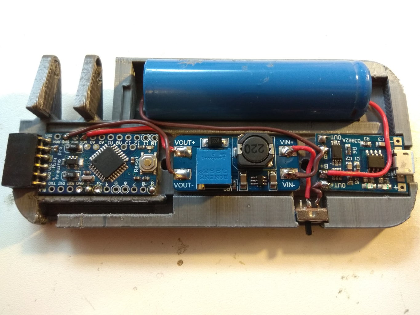
Use double sided sticky tape to secure boards , battery and switch to bottom plate like shown in the picture.
switch needs to be pushed all the way to the edge of bottom plate. Solder wires like shown on picture.Also this picture shows it poorly but make shure no wires are above holes.
Wiring connections :
- positive of battery to B+ of battery charger
- negative of battery to B- of battery charger
- B- or OUT - (they are same thing) to the Vin- on boost converter
- OUT + of battery charger to the one leg of the switch
- leg next to it to the Vin + on boost converter
Step 8: Assembly 2

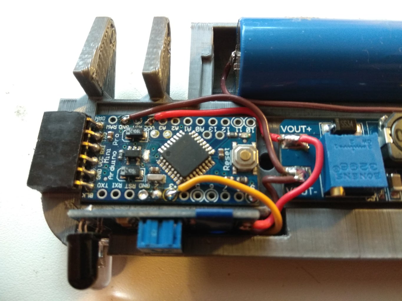
solder female pin headers like shown on picture . Trick is to stick arduino pro mini on bottom plate with double sided sticky tape and then just bend the legs of header and solder it.
Step 9: Assembly 3
Solder vout + to vcc and vout - to the gnd on arduino board.
Step 10: Assembly 4
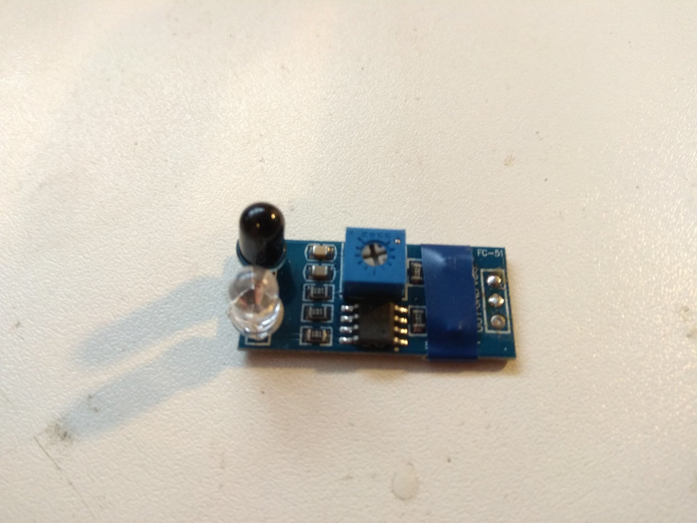
if your IR sensor does not have leds bent like this just bend them.Desolder any header pins if there are any soldered . Also take black ,grey,blue or any darker colour of insulating tape and tape it across leds like shown on picture.Your module should look like that at the end.
Step 11: Assembly 5
Check if your IR module fits in hole like shown in picture.If it does not sand out edges a bit .After it fits inside solder out pin on IR Module to the D3 and VCC to VCC and GND to GND .
Step 12: Assembly 6

Take 4 female connectors and cut of the ends.Make shure they are around 80 mm in lenght. Now solder wires to gnd,vcc,A4 and A5. After that you should be able to connect those 4 female connectors to the pins on oled display.
GND on arduino to GND on oled
VCC on arduino to VCC on oled
A5 on arduino to SCL on oled
A4 on arduino to SCA on oled
Make shure wires are not covering M3 holes.
Step 13: Finishing Touches and Code
put 2 M3 nuts on bottom part .After that join bottom and top part and connect them together with 2 M3 15 mm screws. If you see that there are wires covering holes try to move them away with tweezers.Now we are done with assembly . Go to github repository of the project and download rpm_tacho_display.ino code to your arduino pro mini .You will need to use USB to ttl serial adapter module to program your arduino.


