

Introduction: Arduino WiFi Tetris Clock


It’s iconic falling blocks are instantly recognizable to almost anyone, regardless of their interest in video games. But instead of using the blocks to clear lines, we are going to use them to tell time!
This project draws out the digits of a clock using the classic Tetris shapes on a LED Matrix display.
Measuring in at roughly 19cm x 9.5cm, this is physically quite a large display which is very bright, so the result is incredibly eye catching.
Another twist with this project is, unlike traditional Arduino clock projects, it does not use a RTC module for keeping time, instead the time for the clock is set from the internet. One big advantage of this is that you only need to set your timezone and the clock will automatically display the correct time, it will even adjust for daylight savings.
This is a surprisingly easy project to put together that should only take a couple of hours in total, so armed with this guide you should have no excuses to not make one!
Supplies
- P3 64x32 RGB LED Matrix - Aliexpress*
- ESP32 Development Board - Personally I use the ESP32 Dev kit mini (Aliexpress* / Amazon*)
- 5V Power Supply - 4 Amp or larger should do the trick - Aliexpress*
- 20cm Female to Female Dupont cables
- Female Barrel Jack to screw terminal adaptor - Depends on what head is on your power supply
- 3D printed stands for the LED Matrix - Or something to keep it upright!
* = Affiliate Link
Step 1: The Video
I made a video on this topic that you can check out here!
Step 2: LED Matrix Panels
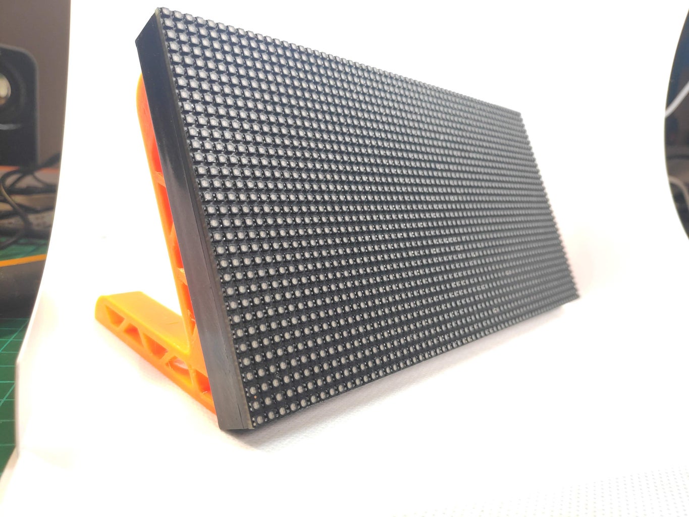


I love these displays! The are a fantastic way of quickly building a really striking arudino project. The intended purpose for these displays is to chained together to make up huge screens as seen at concerts etc, but they can be controlled individually using a microcontroller. The displays come in a lot of different configurations, but I used a 64x32 P3 Matrix for this project.
A display with a resolution of 64 x 32 means it will have 64 LEDs across
and 32 LEDs down. This project is coded to work on 64 x 32 displays, but it could be adapted for other ones if needed.
The "P3" part indicates that the display has a pitch of 3mm. Displays with larger pitches will be physically bigger.
These displays can be driven with lots of different microcontrollers, people commonly use them with Raspberry Pis, but for this project we are going to use an ESP32. An ESP32 is an inexpensive, Arduino compatible, microcontroller with built in WiFi.
The stands are 3d printed and you can find them on thingiverse. They were an existing design I remixed using Tinkercad.
Step 3: Matrix Shields

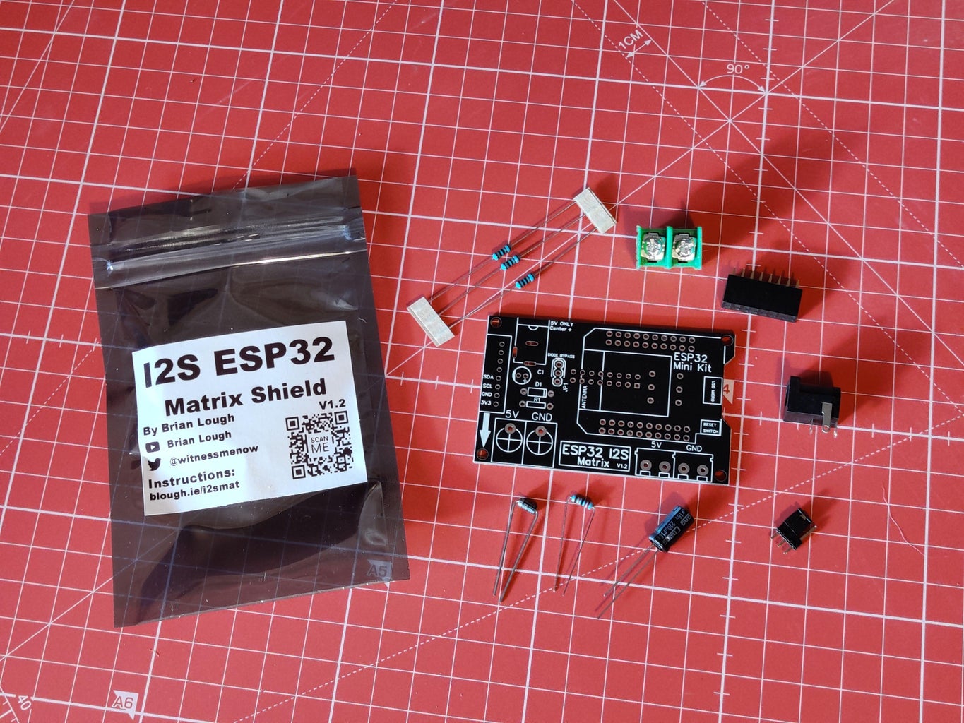
I have made a PCB that makes using these displays really easy! These are not necessary, but they do make them much easier to use.
The original one makes use of PxMatrix library and the new I2S Matrix makes use if the HuB75 DMA library. There is a version of the code for both of them. For more information on the differences between the two libraries, check out this link.
If you are interested in buying one, I sell them on my tindie store.
If you are based in the UK, Colin Hickey also sells them on his store
Step 4: Wiring Without the Shields


First thing we need to do is connect the power supply up to the wires that came with the display. For this I useda couple of screw terminals and piece of perfboard to make a small board for connecting the power supply to the wires, I was happy with how it turned out!
Adafruit in their learn guides recommend connecting the wire directly to the barrel jack connector as pictured above, but I couldn't get this to make a solid connection (physically), but who am I to question what Adafruit suggest! If you do go down this route make sure to use some insulating tape or heatskrink to give it some strength.
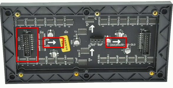
The next thing we need to do is wire up the ESP32 to the matrix panel. The connector that has the arrows moving away from it is "P-In" and the ESP32 will be connected to that, but before we connect that, we need to connect some of the P-in connectors to the P-out connector (the one that the arrows are moving towards). You need to connect the following:
P-in -> P-out
R2 -> R1
G1 -> R2
G2 -> G1
B1 -> G2
B2 -> B1
For the ESP32 you will need to connect the following:
P-in -> ESP32
A -> 19
B -> 23
C -> 18
D -> 5
E -> 15
STB/LAT -> 22
P_OE -> 2
CLK -> 14
R1 -> 13
If you are using a Adafruit Feather Huzzah 32, use pin 21 for P_OE as it does not have a 2 pin.
Step 5: ESP32 Software Setup

If you are not already setup for programming an ESP32, you will need to do the following
First you will need to download the Arduino IDE from the Arduino website and install it - https://www.arduino.cc/en/Main/Software
Next you will need to setup the Arduino IDE to be used with an ESP32. Open the Arduino IDE, go to File->Preferences and paste following URL into the Additional Boards Manager URLs and click "OK".
https://raw.githubusercontent.com/espressif/arduino-esp32/gh-pages/package_esp32_index.json
Back on the main screen of the Arduino IDE, Tools->Board->Boards Manager when this screen opens search for “ESP32” and install it, this may take a few minutes depending on your internet connection.
After setting up a new board it is recommended to get a simple blink sketch before trying anything more complicated, this can save a huge amount of headaches down the line!
Step 6: Code Setup

The code for this project is available on Github. To install it:
- Go to the project's github page.
- Click the Clone or Download button on the right side of the page and then Download Zip.
- Extract the zip file.
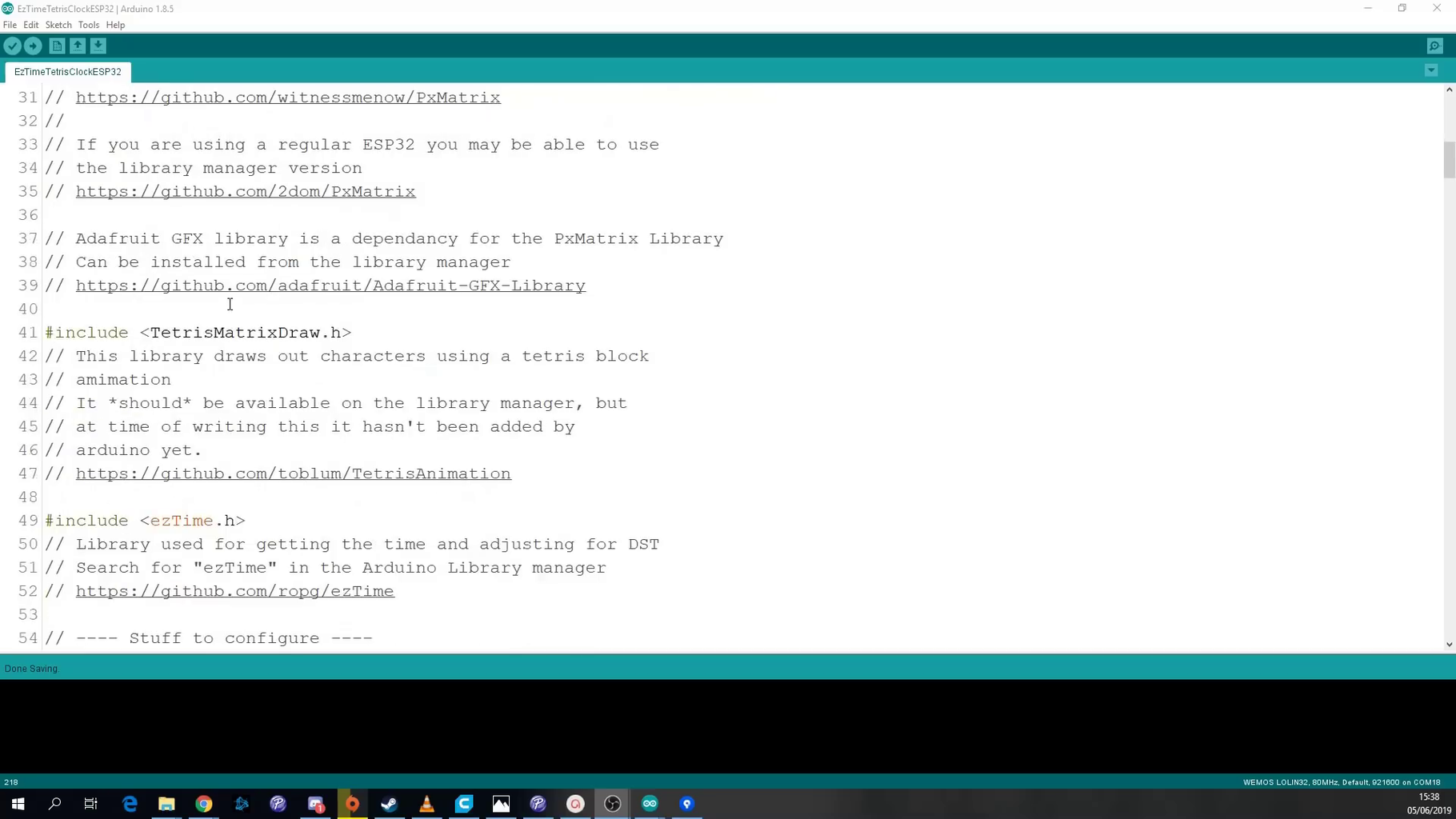
- Inside the extracted folder open up the "ESP32 or TinyPICO" folder, then the EzTimeTetrisClockESP32 folder and open the EzTimeTetrisClockESP32.ino file.
This sketch requires some additional Arduino libraries to be installed
- Tetris Animation by Tobias Blum - handles the tetris style animating of the clock
- PxMatrix by 2Dom - for controlling the matrix display.
- EzTime by ropg - used to get the time from the internet.
- AdafruitGFX by Adafruit - the base library that PxMatrix is built upon.
Details of which versions of the libraries are needed and where to get them are contained up near the top of the sketch.
After installing these libraries you should click the “verify” button (shaped like a tick) on the EzTimeTetrisClockESP32 sketch to make sure that everything compiles fine.
NOTE: If you are using the I2S matrix shield the code for the project is here and will require you to install the HUB75 I2S DMA library.
Step 7: Code Configuraiton


You will need to make a couple of changes to the sketch so that the clock functions correctly for you. Inside the “Stuff to configure section”, set your SSID and password for your WiFi.
Just below that set your timezone in the format “Europe/Dublin”, a link with full list of possible time zones is a comment in the sketch.
And finally if you are using a different ESP32 board than the TinyPICO you will need to change the wiring. Search for “Generic” in the sketch and uncomment the two lines that you find, and comment out the adjacent lines that contain a “TinyPICO” comment.
When finished configuring, upload the code to your ESP32 and you should see it animating in all it’s blocky glory!
Other Adjustments:
There are several adjustments you can make to the clock to so it works exactly as you would like it.
If you would prefer a clock with a 24 hour format, set the twelveHourFormat to false.
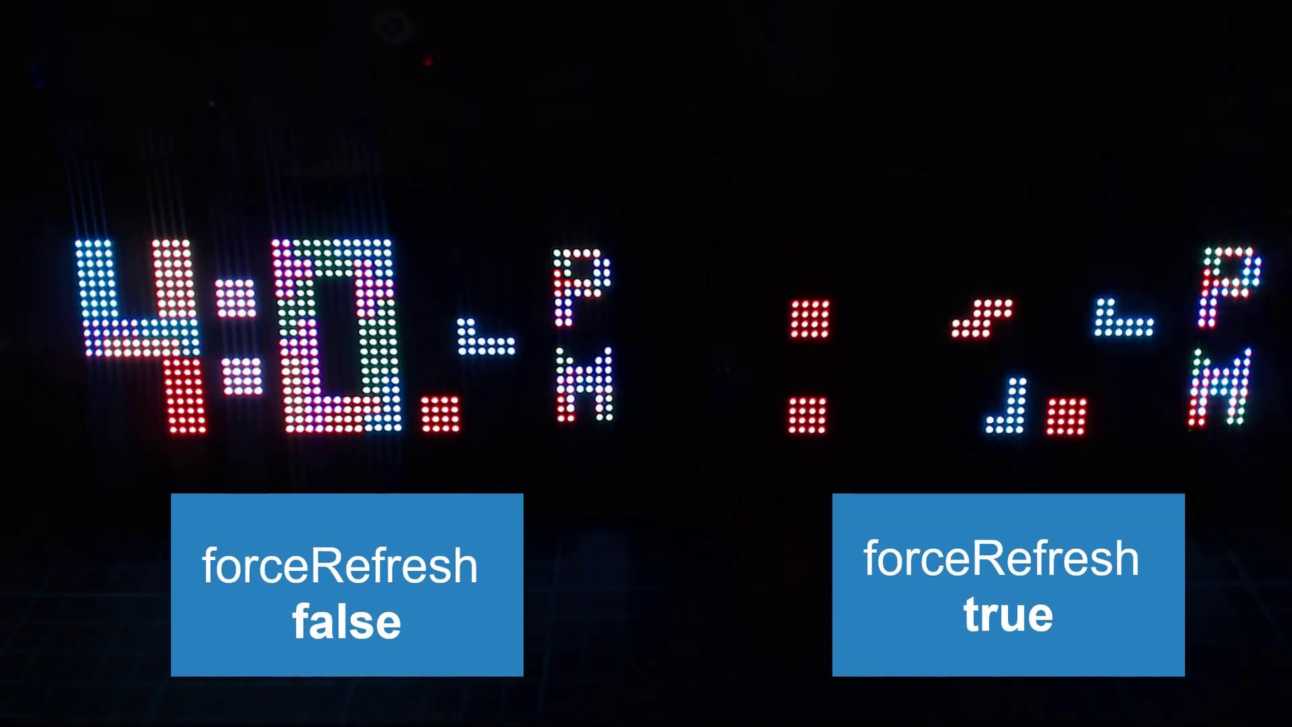
The forceRefresh option controls how many of the digits get drawn every minute. If it is set to true, the entire clock will be cleared and it will draw all the digits again. If set to false, it will clear only the digits it needs to e.g. if the time was currently “10:29” and it needed to update, only the “2” and the “9” would be replaced, the “10” would remain on screen.
And finally, you can adjust the speed of which the tetris blocks fall by changing the value that triggers the animationTimer. By default in the sketch it’s set to 100000, which is 100,000 microseconds, or 0.1 of a second. Reducing this number will make the blocks falling faster. Changing the value to 50000 will result in the animation being twice as fast.
Once you’ve made those changes, upload the code again and you’ll have the clock working just the way you like. All that’s left to do is to waste away the time watching the blocks fall!
Step 8: Thanks for Reading!

Hopefully you enjoy the project! I would love to see your build if you try it out!

Judges Prize in the
Clocks Speed Challenge


