

Introduction: Arduino Controlled Lights


Hello, my name is Blane Parker, I am 14 years old, and live in Texas. I love to play with electronics and visit instructables often to learn; to become better in electronics.
1. What did you make?
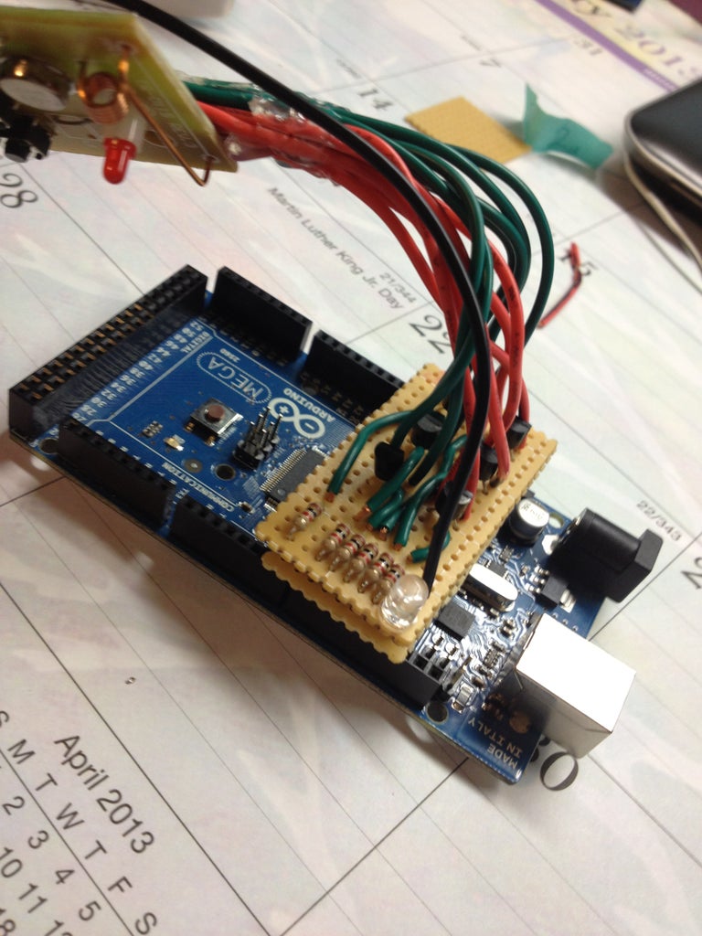
I made device that plugs into an Arduino or a “shield” that controls any outlet via RF. The Arduino can then be sent serial commands to turn on or off a device. .
2. How did you make it?
The idea came about when i was laying in bed with a hurt foot, I wanted to turn off my lights, but I could not get up. Then I got the thought to make the lights remote controlled.
From the knowledge and materials I had, I came up with simple design using cheap parts to create the product.
3. Where did you make it?
I built it at home, but I got some of the parts from Radio Shack and Home Depot. And as soon as I was finished I set it up in my room. After a couple of hours flickering my lights via serial, I programed a simple voice interface using GlovePie. This is because it is easy to program and I could add a remote, such as a wiimote.
3. What did you learn?
The main thing i learned is to check all lines for bridges after soldering. If not, you could easily destroy the circuit or worse, your computer. Throughout the build I became better in all my skills including soldering, programming, logic, and creativity.
Step 1: Materials

Parts
6-2n3904 transistors (pack of 20) - $2.87
http://www.amazon.com/Amico-2N3904-Through-Bipolar-Transistors/dp/B008IFYEP6/
1-Wireless remote control - $19.97
http://www.homedepot.com/p/Verdant-Electronics-Indoor-Wireless-Remote-Control-Kit-RC-015-3/202353567
6-1k Resistors (pack of 25) - 1.29
http://www.amazon.com/E-Projects-4X-8Y1R-PT71-Resistors-Watt-Pieces/dp/B00B5R8950/
Perfboard - $3.49
http://www.radioshack.com/product/index.jsp?productId=2103804
Arduino
Wire
Tools
Soldering iron & solder
Hot glue gun & glue sticks
Dremal
Computer with Arduino IDE installed
Step 2: Take It Apart


First, take apart the remote.
I did this by removing a single screw behind the battery, then snapping the cover off. Inside you should find a single circuit board and a battery.
Next, make some room inside
You will need some room inside the remote to run wires. To do this: just use a blade or sanding attachment for the dremel and cut away the notches in the back. You will also need to make and opening in the back to run wires out of.
Step 3: Wire the Remote


Solder the wires to the remote
You will first need to find 2 contacts on each of the pushbuttons that run back to the chip or battery. Before you start soldering all of the wires, check to see if there is a common ground because it can save you a lot of soldering.
Check the wires
If done correctly, you should be able to cross the wires of a single contact and trigger the remote. Once you get everything working, mark the wires corresponding with the pushbutton and add some hot glue as a strain relief.
Check polarity
By using a diode or an LED, check the polarity of each set of wires and mark the positive and ground of each button. This can be done by touching the leads on the diode to the wires, if it triggers, then mark the postive of the diode to the corrasponding wire.
Step 4: Build the Circuit


Fit the Board
Find out how big you need to make the board and mark out the location of the components
Build the circuit
Follow the schematic and solder the components into place.
Step 5: Solder the Wires to the Board


Solder the wires on the new "shield"
Go ahead and solder the wires to the correct side of the transistor, checking each time to make sure that you have the polarity right.
Check your work
Now that you are finished, check the solder joints for shorts, bridges, and missed connections.
Step 6: Finished and Extensions

Set it up
Finish it by plugging in the shield, then upload the code. Sample code at the bottom of the page.
Taking it further
You can easily interface this with pretty much anything. Here are some of my ideas...
•Ethernet shield
•World wide light controller
•Twitter controlled
•SiriProxy
•PIR/Ultrasonic sensor
•Motion detecting lights
•Home automation- by detecting the direction you're walking to turn on and off the lights
•Capacitive sensor
•Touch pad controller
•Touch the actual object to toggle it
CODE:
/*
You can redistribute and/or modify this code under the terms of the GNU General Public License as published by Blane Parker (blanepark@gmail.com)
*/
const int aon = 12;
const int bon = 11;
const int con = 10;
const int aoff = 9;
const int boff = 8;
const int coff = 7;
int incomingByte;
void setup() {
Serial.begin(9600);
pinMode(aon, OUTPUT);
pinMode(bon, OUTPUT);
pinMode(con, OUTPUT);
pinMode(aoff, OUTPUT);
pinMode(boff, OUTPUT);
pinMode(coff, OUTPUT);
}
void loop() {
if (Serial.available() > 0) {
incomingByte = Serial.read();
if (incomingByte == '1') {
digitalWrite(aon, HIGH);
delay(600);
digitalWrite(aon, LOW);
}
if (incomingByte == '2') {
digitalWrite(bon, HIGH);
delay(600);
digitalWrite(bon, LOW);
}
if (incomingByte == '3') {
digitalWrite(con, HIGH);
delay(600);
digitalWrite(con, LOW);
}
if (incomingByte == '4') {
digitalWrite(aoff, HIGH);
delay(600);
digitalWrite(aoff, LOW);
}
if (incomingByte == '5') {
digitalWrite(boff, HIGH);
delay(600);
digitalWrite(boff, LOW);
}
if (incomingByte == '6') {
digitalWrite(coff, HIGH);
delay(600);
digitalWrite(coff, LOW);
}
}
}

Participated in the
Make-to-Learn Youth Contest

Participated in the
Lamps & Lighting Contest


