

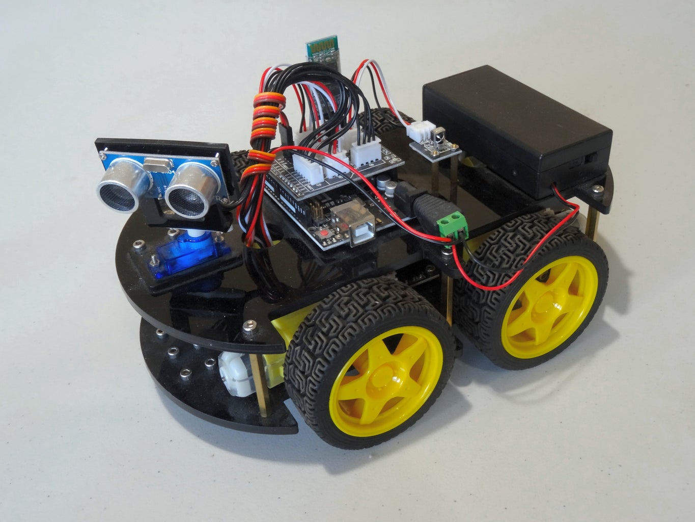
Introduction: Assemble Elegoo Arduino Robot Version 2.0


Last year I posted a tutorial on assembling Elegoo Smart Car Robot Kit Version 1.
This was a very nice KIT, however since then the great Elegoo people introduced improved Version 2, and Version 3 of the Robot, and sent me both versions so I can add support for the Robot in Visuino.
Version 3 is the best, however, since some people may have gotten Version 2, I will post the Assembly tutorial for it first, and then will follow with tutorial for the Version 3 of the KIT.
After that I will post tutorials on programming the Robot with Visuino for remote control, obstacle avoidance, and line following, so stay tuned... ;-)
Here you can also see the Unboxing Video of the KIT.
Step 1: Assemble the Motors
- Take the Motors, and the Aluminium Blocks from the bags
- Mount the Aluminium Blocks on the side of the motors that is flat (opposite of the pin in the center of the gearbox)
- For each motor, take 2 long bolts from the bag of bolts and nuts for the Motors
- Insert the bolts through the aluminium blocks and then through the motor gear
- For each motor, take 2 nuts from the bag of bolts and nuts for the Motors, and tighten them on the bolts
Step 2: Install the Motors on the Chassis
- Take Bottom Layer (baseplate) of the chassis (the one that does not have the rectangle hole it front) from the bag
- Peel off the protective paper layer
- Place the motors on top the the layer with the threaded holes pointing down toward the chassis layer (baseplate), over the 2 small holes per motor locations of the chassis layer
- Make sure the motors are placed with the wires on the inside of the cassis, and the motors pointing away from the center of the chassis
- Take the short bolts from the bag of bolts and nuts for the motors, and use 2 of them per motor to tighten the motors to the chassis layer (baseplate)
Step 3: Install the Motor Driver Board
- Remove the L298N Motor Driver Board from the protective bag
- Place the L298N Motor Driver Board in the center of the chassis layer(baseplate) with the heat sink(the big metal aluminium block) pointing toward the back of the chassis(the front has 6 small holes, the back does not have holes)
- Take 4 bolts from the bag of bolts and nuts for the UNO and L298N
- Insert the bolts through the holes in the 4 corners of the L298N Motor Driver Board
- Insert the bolts through the 4 holes in the center of the chassis layer
- Take 4 nuts from the bag of bolts and nuts for the UNO and L298N
- Tighten the nuts on the bolts on the bottom of the chassis layer (Do not overtighten, as you may bend and damage the board!)
- Insert the connectors of the 4 motors to the corresponding(the closest) 4 connection points on the side of the L298N Motor Driver Board as shown in the Video
Step 4: Install the Line Following Sensors
- Take the Line Following Sensor Modules from the protective bag
- Take 2 brass standoffs from the bag of bolts, standoffs and nuts for the Line Following Sensors
- Insert the male threaded side of the standoffs into the 2 holes of one of the Line Following Sensor Modules from below the board (the side opposite of the components)
- Take 2 nuts from the bag of bolts, standoffs and nuts for the Line Following Sensors
- Tighten the nuts on the male threads of the brass standoffs
- Repeat the same steps 2, to 5 for the other 2 sensors
- Place the Line Following Sensor Modules on the bottom side (the opposite of the motors) of the chassis layer, at the front where there are 6 small holes matching the positions of the standoffs, in such a way that the standoffs are placed on to of the holes with their female threaded side, and the sensor connector points toward the center of the chassis
- Take 6 bolts from the bag of bolts, standoffs and nuts for the Line Following Sensors
- Insert the bolts through the 6 holes, from the top of the chassis layer(baseplate) into the female threaded sides of the standoffs, and tighten them
Step 5: Install the Arduino Board and the Sensors Shield
- Take top layer (baseplate) the chassis (the one that does have the rectangle hole it front) from the bag
- Peel off the protective paper layer
- Take the Arduino UNO from the protective bag
- Place the Arduino UNO on top of the chassis layer, in the center, and rotate it until the 3 mounting holes on the chassis layer match 3 of the mounting holes on the Arduino UNO. If you can't match them, flip the chassis layer over and try again
- Take 3 bolts from the bag of bolts and nuts for the UNO and L298N
- Insert the bolts through the 3 holes of the Arduino UNO that have matching holes on the chassis layer
- Insert the bolts through the 3 holes in the center of the chassis layer
- Take 3 nuts from the bag of bolts and nuts for the UNO and L298N
- Tighten the nuts on the bolts on the bottom of the chassis layer
- Take the Sensor Shield from the protective bag
- Place the Sensor Shield on top of the Arduino UNO matching the pins on the shield with the holes on the Arduino UNO pin headers as shown in the Video
Step 6: Install the Infrared Remote Receiver
- Take the Infrared Remote Receiver Module out of the bag
- The 2 brass standoffs from the bag of bolts, standoffs and nuts for the IR Module
- Insert the male threaded side of the standoffs into the 2 holes of one of the Infrared Remote Receiver Module from below the board (the side opposite of the components)
- Take 2 nuts from the bag of bolts, standoffs and nuts for the IR Module
- Tighten the nuts on the male threads of the brass standoffs
- Place the Infrared Remote Receiver Module on top of the chassis layer, behind the Sensor Shield, where there are 2 really small holes matching the positions of the standoffs, in such a way that the standoffs are placed on to of the holes with their female threaded side, and the sensor connector points toward the center of the chassis
- Take 2 bolts from the bag of bolts, standoffs and nuts for the IR Module
- Insert the bolts through the 2 holes, from the bottom of the chassis layer(baseplate) into the female threaded sides of the standoffs, and tighten them
Step 7: Install the Battery Box
- Take the Battery Box from the protective bag
- Open the box, and take out the power connector for the Arduino UNO
- Place the Battery Box at the back of the upper layer(baseplate) of the chassis on the back, behind the Infrared Receiver Module, matching the 4 holes on the bottom of the Battery Box, with the 4 holes on the chassis layer
- Make sure the switch and the cables are on the same side of the chassis as the power and USB connectors of the Arduino UNO
- Take 4 bolts from the bag of bolts and nuts For Cell Box
- Insert the bolts from the top through the holes on the bottom of the Battery Box and through the holes of the chassis layer
- Take 4 nuts from the bag of bolts and nuts For Cell Box
- Tighten the nuts on the bolts from underneath the chassis layer
- Take the Power connector for the Arduino UNO
- Use screwdriver to loosen the 2 bolts of the 2 connection points ( "+" and "-" ) on the connector
- Take the cable with the red and black wires, and a small connector on the other end
- Insert the Red Wire of the cable with the small connector on the other end into the "+" connection point of the Power Connector for the Arduino UNO
- Insert the Red Wire from the Battery Box into the same "+" connection point of the Power Connector for the Arduino UNO
- Use screwdriver to tighten the bolt of the "+" connection point of the Power Connector for the Arduino UNO
- Insert the Black wire of the cable with the small connector on the other end into the - connection point of the Power Connector for the Arduino UNO
- Insert the Black wire from the Battery Box into the same "-" connection point of the Power Connector for the Arduino UNO
- Use screwdriver to tighten the bolt of the "-" connection point of the Power Connector for the Arduino UNO
- Plug the Power Connector into the Arduino UNO
Step 8: Installing the Servo Turning the Ultrasonic Ranger
- Take the flat Servo Holding Board from the bag of Servo Mount And Servo Holding Board
- Peel the protective paper from the board
- Take the Servo from the plastic bag
- Insert the cable of the Servo through the big rectangle hole of the Servo Holding Board
- Insert the Servo through the rectangle hole in such a way that when the 3 bigger round holes are pointing away from you, the Servo shaft is pointing upwards, and is on the right side as shown in the Video
- Take the 2 small bolts shown in the Video and insert them from below through the 2 really small holes in the Servo Holding Board on the 2 sides of the Servo
- Take 2 small nuts and tighten them on the bolts over the 2 mounting points of the Servo as shown in the Video
- Insert the Servo cable from the top, through the rectangle shaped hole at the front of the upper layer(baseplate) of the chassis
- Insert the bottom part of the Servo from the top, through the rectangle shaped hole at the front of the upper layer(baseplate) of the chassis with the servo shaft located closer to the center of the chassis, and the 3 holes of the Servo Holding Board matching the 3 holes on the chassis layer
- Take 3 big bolts from the bag of bolts and nuts for the Servo mount and Insert them from the top through the 3 holes of the Servo Holding Board, and then through the chassis layer
- Take 3 matching big nuts from the bag of bolts and nuts for the Servo, and tighten them on the bolts from below the chassis layer
Step 9: Assemble the Ultrasonic Ranger
- Take the Ultrasonic Ranger Mount from the plastic bag
- Peel the protective paper layer
- Take the Ultrasonic Ranger from the plastic bag
- Take 4 small bolts from the bag of bolts for the Ultrasonic Ranger
- Insert the 4 bolts through the 4 holes in the corners of the Ultrasonic Ranger from the side where the sensors are mounted toward the back of the board
- Insert the 4 bolts into the 4 holes of the Ultrasonic Ranger mount as shown in the Video
- Take 4 small matching nuts from the bag of bolts for the Ultrasonic Ranger, and tighten them on the bolts
Step 10: Installing the Ultrasonic Ranger on the Servo
- Take the symmetric straight Servo Seat from the bag of Servo Seats from the bag of
- Place it on top of the Servo shaft
- Take the small screw from the bag of Servo Seats, and use it to tighten the seat to the Servo shaft
- Take the the Servo Mount, and place it on top of the Seat as shown in the Video
- Take the remaining 2 small screws from the bag of Servo Seats, and use them to tighten the Servo Mount to the Seat
Step 11: Installing the Standoffs/Spacers on the Chassis
- Take one Brass Standoff from the bag for plastic baseplates
- Place it below of one of the 6 side holes of the upper layer (baseplate) of the chassis
- Take a bolt from the bag for plastic baseplates
- Insert the bolt from the top of the chassis layer through the hole into the threaded hole of the brass standoff, and tighten it
- Repeat steps 1 to 4 for the other 5 standoffs, and holes on the chassis layer
Step 12: Start Connecting the Cables
- Take the cables out of the plastic bag
- Take the 6 Wire Cable and connect one end to the 6 Pin Connector on the L298N Motor Driver Board on lower layer(baseplate) of the chassis
- Take the 4 Wire Cable and connect it to the Ultrasonic Ranger on the upper layer of the chassis
- Connect the other end of the 4 Wire Cable to the 4 Pin Connector on the Sensor Shield marked "Ultrasonic Sensor"
- Connect the Short 3 Wire Cable to the Infrared Remote Receiver Module on the upper layer of the chassis
- Connect the other end of the Short 3 Wire Cable to the 3 Pin Connector on the Sensor Shield marked "Infrared Sensor"
- Connect the 3 Long 3 Wire Cables to the 3 Line Following Sensors underneath the bottom layer of the chassis
- Push the 3 Long 3 Wire Cables from below through the big hole on the bottom layer behind the Line Following Sensors so the cables will appear on top of the bottom layer of the chassis
- Take the 4 wires of the bottom layer of the chassis, and push them from below through the big hole at the front of the upper layer behind the Servo
- Take the cable from the Servo, and push it from below through the same big hole at the front of the upper layer behind the Servo
Step 13: Join the 2 Layers of the Chassis Together and Finish Connecting the Cables
- Make sure the top layer(baseplate) of the chassis with its standoffs is placed properly on the bottom layer with the side holes on the bottom layers matching the threaded holes on the bottom of the standoffs
- Take a bolt from the bag for plastic baseplates
- Insert the bolt from underneath the bottom layer of the chassis through the hole into the threaded hole of the brass standoff, and tighten it
- Repeat steps 1 to 4 for the other 5 standoffs, and holes on the bottom chassis layer
- Take the unconnected end of the 6 Wire Cable from the Motor Driver Board, and connect it to the 6 Pin Connector on the Sensor Shield
- Connect the 3 Wire Cable from the Left Line Following Sensor (when looking the Robot from the back) to the Left 3 Pin Connector on the Sensor Shield marked "Line Tracking Module (3)"
- Connect the 3 Wire Cable from the Center Line Following Sensor to the Center 3 Pin Connector on the Sensor Shield marked "Line Tracking Module (2)"
- Connect the 3 Wire Cable from the Right Line Following Sensor (when looking the Robot from the back) to the Right 3 Pin Connector on the Sensor Shield marked "Line Tracking Module (1)"
- Connect the 3 Wire Cable from the Servo into the 3 Pin Connector on the Sensor Shield marked "SG90", in such way that the Brown Wire is connected to the "GND" pin and the Orange Wire is connected to "SG" pin
- Take the 2 Wire Power Cable from the Arduino UNO power connector, and push it from the top through big hole at the front of the upper layer behind the Servo
- Connect the 2 Wire Power Cable from the Arduino UNO to the 2 Pin Power Connector on the Motor Driver Module on the bottom layer of the chassis
Step 14: Install the Wheels
- Take the Wheels from the plastic bag
- Take one of the wheels. The hole in the center has 2 flat sides. The shafts on the Gear Boxes of the motors have the same shape. Rotate the Wheel until the orientation of shape of the hole on the Wheel, matches the orientation of the shaft, and plug the wheel on the shaft
- Repeat the same step 2 for the remaining 3 wheels
Step 15: Charge and Install the Batteries
- Take the Battery Charger out of the plastic bag
- Insert its Power Cable into the Battery Charger
- Take the Batteries out of the protective box
- Place the Batteries into the Battery Charger, making sure to match the indicated +/- polarity
- Connect the charger to power outlet to charge the batteries. The LEDs on the charger will turn RED indicating that the batteries are charging
- When the batteries are fully charged the LEDs will turn GREEN
- Disconnect the Charger from the power outlet
- Make sure the Battery Box On/Off Switch is in Off position
- Open the Battery Box by sliding it in the indicated direction
- Remove the Batteries from the Battery Charger
- Place the Batteries into the Battery Box, making sure to match the indicated +/- polarity
- Place the Battery Box cover and slide it to close the Battery Box
- Turn the Battery Box Switch to On Position to test the Batteries
- Turn Battery Box Switch to Off Position
Step 16: Optionally: Install the Bluetooth HC 06 Module
For some projects the robot may need to be connected over Bluetooth. The Robot KIT includes an optional HC-06 Bluetooth Module, that can be installed on the Sensor Shield. The Module should always be removed when programming the Robot, since it uses the same Serial Communication channel that is also used to program the Arduino UNO.
- Take the HC-06 Bluetooth Module from the plastic bag
- Insert the HC-06 Bluetooth Module into the 4 Pin Female Connector on top of the Sensor Shield in such a way that the "VCC" Pin of the Module is connected to the "+5V" connection point of the connector, and the "RXD" Pin of the Module is connected to the "TDX" connection point of the connector
Step 17: Optionally: Tidy Up the Cables
To reduce the cable clutter, you can use the Servo Cable to tighten the cables together.
- Unplug the Connector of the Servo Cable from the Sensor Shield
- Folding the as many as possible of the rest of the cables together, start wrapping the Servo Cable around them
- Make sure you leave enough cable to the Ultrasonic Ranger so it will be able to turn left and right without any problems
- Once the cables are well wrapped with the Servo Cable, plug back the Connector of the Servo into its connection point on the Sensor Shield
Step 18: Center the Ultrasonic Ranger on the Servo


Before we can make any projects using the Ultrasonic Ranger, we need to make sure that it is mounted properly oriented on top of the Servo.
For this the simplest way is to use Visuino to generate the Arduino code for us.
- If you don't have the Arduino IDE installed, download it from www.arduino.cc/en/Main/Software and install it
- If you don't have Visuino installed, download it from www.visuino.com and install it
- Start Visuino
- Click on the "Drop Down" button in the corner of the Arduino Component in the design area
- From the Menu select "Add Shields..."
- In the right view of the Shields Dialog, Expand the "Elegoo" category
- Select the "Elegoo Robot V2 Shield"
- Click on the "+" button above the left view, to add the Shield
- Close the Dialog
- In Visuino, Press F9 or click on the button shown on Picture 5 to generate the Arduino code, and open the Arduino IDE
- If the HC-06 Bluetooth Module is installed on the Sensor Shield, remove it
- Connect the Arduino UNO to the computer with USB Cable
- In the Arduino IDE make sure "Arduino/Genuino Uno" is selected as board
- In the Arduino IDE make sure the "Com Port" where the Robot is connected is selected
- In the Arduino IDE, click on the Upload button, to compile and upload the code (Picture 6)
- When the code is uploaded the Servo will rotate to Center Position
- If the Ultrasonic Ranger does not point forward, remove the cable connected to the Ultrasonic Ranger
- Use the small Philips type screwdriver from the set to unscrew the screw holding the Ultrasonic Ranger's Mount to the Servo Shaft
- Remove the Ultrasonic Ranger Mount, rotate it to point the Ultrasonic Ranger forward and place it back on the Servo Shaft
- Tighten the Screw
- Connect the Ultrasonic Ranger's Cable to the Ultrasonic Ranger's connector
- Turn On Power to test if the Servo is properly centered
- Turn Off the Power

Participated in the
Wheels Contest 2017

Participated in the
Arduino Contest 2017


