

Introduction: Atmega Programming With USBtinyISP and Arduino
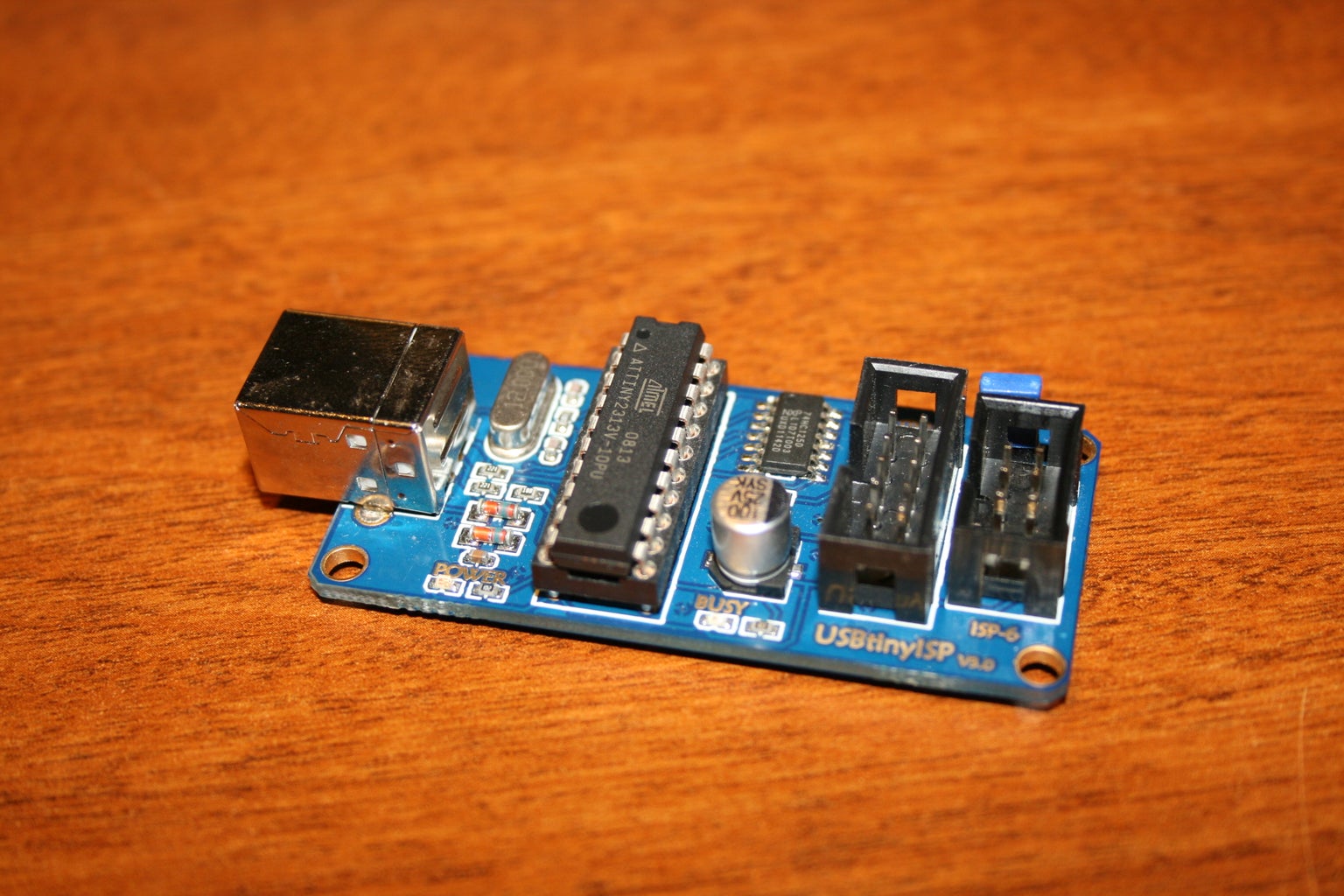


This is to show how you can program an Amtel Atmega chip using a USB AVR programmer. I have chosen the USBtinyISP v3.0 to program. I picked mine up on ebay for i think $10. I will also be using the Arduino software, because it is free and I like the language it uses. You are welcome to use any software you would like, and I will try to post more tutorials on using different software options as I get around to them.
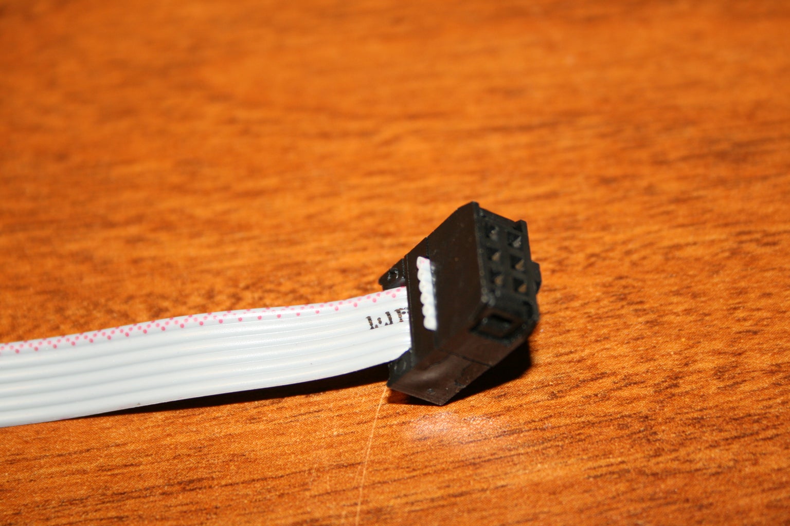
First download the software from arduino.cc. Next we will need to set up header pins for our AVR programmer. To program the Atmega328 I am using here we are going to need the 6 pin header. Be very careful with the images I have posted. They are from the Arduino website. The one labeling each of the pins can be misleading. You need to pay special attention the actual numbers of each pin. Compare the second image and third image above to understand where pin number 1 is.
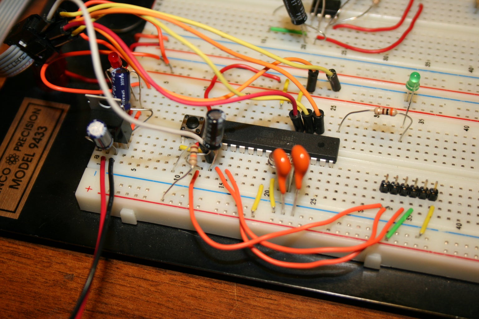
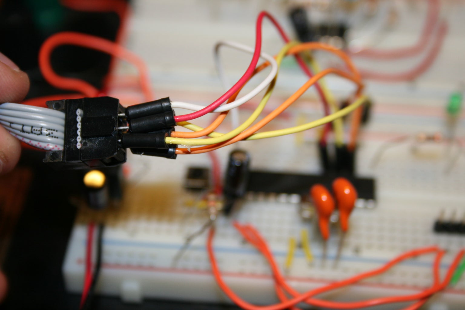
First make your connections to the Atmega328. There are 3 data connections, 1 reset, and 2 power/ground connections. (making up the 6 pin header)
Once you have made sure all six connections are correct, plug your ISP programmer into your computer and the 6 pin header into the ISP programmer.
You should see the power light come on on the ISP programmer. Make sure you have downloaded the driver for the programmer. I had some issues with installing the driver. I ended up needing to go into my computer's device manager, select the programmer and choose update driver, and then manually direct it to the driver installer. It was a pain, but once I did that everything was working correctly.
Next open up arduino. For this tutorial we are going to just use the Blink example program. I have changed the LED pin to Digital pin 9 though. The reason for doing this is because we cannot have any low-impedance (resistance) on any of the pins the ISP programmer uses. the original pin in the arduino example is 13, which is the pin that the SCK connection uses.
So open up the "BLINK" example and change the LED pin to pin 9.
Next we have two options. Either you can hold shift and press upload, or go to file>upload using programmer.
either way, it should verify your program, then the busy LED on the ISP programmer should flash, and the program should be uploaded to the atmega328.
And that should be it. Place a resistor and LED on pin 9 (the bottom right pin) and it should flash on and off
Thats the easiest set-up to using an ISP programmer. I will hopefully add more options as I am able to get through them.
Now there is one downside to this. You no longer have the serial connection to the arduino software that you do with a normal FTDI connection. The upside is we no-longer need the bootloader, so when our chip is powered, the program starts immediately. You can still use serial commands, you just cant watch them in the serial monitor without the FTDI cable connected too.


