

Introduction: Attiny85 Mini-Arduino


This is an Arduino like board that uses an Attiny85 microcontroller. It can be programmed using the Arduino IDE.
You will need:
Adafruit Perma-Proto Quarter-sized Breadboard PCB http://www.adafruit.com/products/1608
2.1mm barrel jack http://www.adafruit.com/products/373
2 10mf electrolytic capacitors https://www.sparkfun.com/products/523
7805 Voltage regulator http://www.adafruit.com/products/2164
330-560 Ohm 1/4 Watt resistor. (purchased locally)
Red 5mm LED (purchased locally)
22 gauge hookup wire (I used Red, Black, and Green, purchased locally)
9 Volt battery clip http://www.adafruit.com/products/80
9 Volt battery. (purchased locally)
Attiny85 micro controller https://www.sparkfun.com/products/9378
8 pin IC socket https://www.sparkfun.com/products/7937
2 IDC breadboard helper http://www.adafruit.com/products/2105
6mm Pushbutton Switch https://www.sparkfun.com/products/9
Tiny AVR Programmer https://www.sparkfun.com/products/11801
6-pin Socket/Socket IDC cable http://www.adafruit.com/products/371
Male Headers https://www.sparkfun.com/products/116
Female Headers https://www.sparkfun.com/products/115
Step 1: The Power Supply

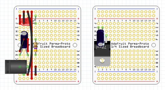
Solder the barrel jack into holes A-1 and A-3 on the board. Solder the lead on the side into Ground Rail-2.
Solder a black wire from E-1 to F-2.
Solder a red wire from E-3 to F-3.
Solder one of the 10mf capacitors in holes D-1 and D-3. The short lead goes in D-1.
Solder a red wire from J-1 to Positive Rail-1.
Solder a black wire from J-2 to Ground Rail-2.
Solder the other 10mf capacitor between I-1 and I-2. The short lead goes in I-2.
Solder the 7805 regulator into holes G-1, G-2, and G-3. The side with the most metal showing points to the Barrel jack.
Solder a red wire from Positive Rail-4 to Positive Rail-4 on the other side.
Solder a black wire from Ground Rail-3 to Ground Rail-3 on the other side.
Solder the 330-560 Ohm resistor between D-5 and F-5, polarity doesn't matter.
Solder the short lead on the red LED into hole J-5 and the long lead into the fifth hole on the positive rail.
Solder a black wire from hole A-5 to the fifth hole in the ground rail on the side with the barrel jack.
This completes the power supply. To test it plug in the battery. The LED should light and the voltage regulator should not get hot.
.
Edited 4/17/16 - Added Fritzing diagram. The image on the right shows the position of the voltage regulator and the capacitor, If they were in the same picture it would get a little busy.
Step 2: Microcontroller Socket and ICSP Header

Solder the In Circuit Serial Programmer (ICSP) header into Holes E-6 through E-8 and F-6 Through F-8. Wrap a small rubber band around it to hold it in place while soldering the first pin.
Solder a red wire from J-6 to Positive Rail-6.
Solder a black wire from J-8 to Ground Rail-8.
Solder the IC socket into holes E-12 through E-15 and F-12 Through F-15. The alignment notch points away from the power supply. Hold it in place with the rubber band.
Solder a black wire from D-8 to G-15. (Reset)
Solder a black wire from J-12 to Ground Rail-12. (Ground)
Solder a red wire from A-15 to Positive Rail-15. (VCC)
Solder a green wire from G-7 to D-12. (MOSI)
Solder a green wire from C-7 to C-14. (SCK)
Solder a green wire from B-6 to B-13.(MISO)
Step 3: The Reset Button

Clip the leads off one side of the 6mm pushbutton switch.
Solder the remaining pins on the switch into J-9 and J-11.
Solder a black wire from H-9 to H-15.
Solder a black wire from I-8 to I-11.
Step 4: Headers


Cut two pieces of the male headers with two pins.
Solder the male headers from the top with the long side down. They go in Ground Rail-14 and 15, and Positive Rain-14 and 15. These pins are used to attach the board to a breadboard, and to activate the power rails on the breadboard.
Cut two pieces of the female headers. One piece with two pins and one with three. Leave enough extra so you can sand the cut edges smooth.
Solder the three pin header into A-12 through A-14.
Solder the two pin header into J-13 and J-14.
Attiny85 Pinouts:
            Reset    1   \/   8  VCC 5 Volts
   Analog In 3, PB3  2        7  PB2, Analog In 1, I2C SCL, SPI SCK
   Analog In 2, PB4  3        6  PB1, PWM, SPI MISO
             Ground  4        5  PB0, PWM, I2C SDA, SPI MOSI<br>
Edited 4/17/16 - Improved picture and added a fritzing diagram.
Step 5: Programmer


Plug the Attiny85 chip into the socket, make sure you have the small alignment dot on the chip at the same end as the notch in the socket.
Solder the 2x3 pin male header from the second IDC breadboard helper into the empty 2x3 space on the Tiny AVR Programmer. The pins point up on the same side as the socket.
If you look closely at the first photo you will notice a small vertical line just to the left of the top left pin. This is the pin number one marker on the Tiny AVR Programmer.
On the board Pin number one is closest to the power supply.
Connect the ICSP cable like in the second photo.
Follow this link for instructions on how to add the Attiny85 definitions to the Arduino IDE:
https://learn.sparkfun.com/tutorials/tiny-avr-programmer-hookup-guide/
Step 6: Testing
Attiny85 Pinouts:
            Reset    1   \/   8  VCC 5 Volts
   Analog In 3, PB3  2        7  PB2, Analog In 1, I2C SCL, SPI SCK
   Analog In 2, PB4  3        6  PB1, PWM, SPI MISO
             Ground  4        5  PB0, PWM, I2C SDA, SPI MOSI
For this test you will need 5 LEDs, 5 resistors 330-560 Ohm 1/4 Watt, and some jumper wires.
Hook up 5 LEDs to pins PB0 - PB4 with a resistor on each LED.
Copy/paste the following code into the Adruino IDE and upload it to your new board:
int LED[] {0,1,2,3,4};

void setup()
{
  for(int i=0;i<5;i++) pinMode(LED[i], OUTPUT);
}

void alloff()
{
  for(int i=0;i<5;i++) digitalWrite(LED[i], LOW);
}

void loop()
{
  for(int i=0;i<5;i++)
  {
    alloff();
    digitalWrite(LED[i], HIGH);
    delay(500);
  }
}
The five LEDs should blink in sequence.


![Tim's Mechanical Spider Leg [LU9685-20CU]](https://content.instructables.com/FFB/5R4I/LVKZ6G6R/FFB5R4ILVKZ6G6R.png?auto=webp&crop=1.2%3A1&frame=1&width=306)


