

Introduction: Beyond the Blocks: Super Duper Rocket With Tinkercad


Let's face it: when you think "model rocket" and "Tinkercad in less than 30 minutes", you probably have an image of a simple cylinder with a cone on top. However, Tinkercad is really powerful under the hood, and the apparently simple set of tools has great creative possibilities.
In this Instructable, I'll show you some techniques that will let you get results that look like those from much more elaborate 3D modeling packages. When we're done, we'll have a slick looking space plane.
You'll need:
- A computer with an Internet connection
- A browser that supports WebGL (Chrome, Firefox and Safari are all good)
- A 3D printer (optional)
Step 1: Getting Started: Using Hollow Material to Trim Shapes


The first technique is one you're probably already familiar with, if you've used Tinkercad. Create a shape, assign the "Hollow" material to it, and you can use it to carve or reshape other shapes.
In this example, we're using this technique to make an engine pod for our space plane.
Add a sphere, then a rectangle. Flatten the rectangle and tuck it under the sphere. Set the material of the rectangle to "hollow" and you've sliced off the bottom of the sphere. Group the two objects, and now you can work with only the trimmed sphere.
Step 2: Using the Ruler Tool for Accurate Manipulation


The next technique is another super useful one. Drag a Ruler onto the workplane from the parts bin on the right: it is listed in the Helpers category.
As soon as you do that, you get all sorts of useful info about a selected object: all the dimensions, as well as its distance from the ruler. You can click on any dimension, type in an number, and it will take effect immediately. This lets you resize and position objects very precisely, avoiding the limitation of the grid spacing.
For this example, we'll take the flattened sphere from the next step, and make it taller and skinnier. Looks like an engine pod already!
Step 3: Embossed Effects (this Is Cool)


Here's where it gets interesting. We're going to combine the previous two techniques to achieve an interesting decorative effect.
First, create a duplicate of the engine pod - it is in the Edit menu.
Now, using the ruler, adjust the dimensions of one copy of the pod to be 1mm smaller in each dimension.
Use the Align tool (tucked away under the Adjust icon) to line up both copies along every axis (height, width, depth). One copy of the pod is now completely hidden inside the other - why? You'll find out!
Make a simple stack of rectangles, each a millimeter thick and with a millimeter of space between each. They're shown in green in the screenshot. Group them so they all act as one.
Place them over the engine pod as shown in the picture, and assign them the hollow material. Now select the rectangles, and the engine pod. Important note: do this by selecting the rectangles, and then pressing Shift and selecting the pod. Don't do it by dragging a selection rectangle around all the objects. This way you are only selecting the outermost of the two copies of the pod.
Now group the two, and click anywhere else on the workplane, and voila! You've achieved an interesting ribbed effect. In effect, the hollow rectangles have cut through the outermost copy of the pod but not the inner one, creating a useful embossed effect.
Step 4: Working With Shape Generators


Now for another technique, using Shape Generators combined with Tinkercad's scaling tools to make wings for our space plane.
If you think the possibilities offered by Tinkercad's primitives are limited, there is another world of possibilities in the Shape Generators. These are shapes defined by short computer programs, often produced by members of the Tinkercad community.
To make the wing of the plane, I want to start with a truncated cone, a cylinder that tapers. Let's look through the shape generators and see what we can find. There is something called a Wedge that looks promising. Add it to the workplane, and a dialog appears that lets you change the dimensions. The first thing we'll do is change the number of sides to 30 - now it appears a lot more like a cone!
Let's tip it on its side, and scale it using the ruler. Turn it a little bit more for a swept wing appearance, and straighten the edges by combining it with a hollow rectangle on each end.
Now we can add it to the engine pod, and we have a wing for our plane.
(Truncated and flattended cones are one of the most useful shapes for adding fins, wings, rudders, etc to your models)
Step 5: Putting It All Together


Let's put it all together.
Duplicate the wing and rotate it by 180 degrees. Use the Align feature to get them perfectly aligned. Make another duplicate, and rotate it by 90 degrees to make a tail fin. You can make that one slight shorter by selecting only the fin (the yellow part) and scaling it.
The fuselage is made by starting with the Paraboloid primitive. For the tail half, stretch it out, turn it upside down and trim off the end using a hollow rectangle, just like we did with the engine pod. For the top half, stretch it out.
If you look closely, you can see that I've embossed windows in the front part of the hull. I used the same technique as for the detailing on the engine pods: duplicate the hull, resize it to 1mm smaller in every dimension, align it with the other copy, and then use hollow cylinders to make the windows.
Step 6: Making the Cockpit Canopy


Finally, let's make the cockpit canopy.
For this, I started with a sphere, and used the ruler to redimension it, stretching it in the vertical dimension and flattening it in the horizontal. I placed it in position on the front hull.
I duplicated it, scaled the copy, and aligned it with the original. (See a pattern developing here?)
Then I made yet another copy, positioned it, made it hollow, and grouped it with the outer copy of the cockpit. This cuts through the outer canopy (grey) revealing the inner canopy (blue), and leaves a nice bezel.
Step 7: Making a 3D Print


Now it's time to print!
One of the great things about Tinkercad is that it can export files that are really just ready to print. They're compact, accurate and don't contain strange errors that can confuse the printer software.
So we save our file as an STL, and import it to the printer software (Makerware in this case). There is an unsupported overhang under the wing, so we should enable support material in the printer options.
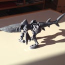
An hour later, we have a print of our fancy space plane!


