

Introduction: Blink for ESP8266 Native, Like Arduino Using Windows


When I bougth the ESP8266, my first thought was to use ESP8266 as a Wifi shield for Arduino. I found out that the ESP8266 is a powerfull device by it self. And I asked myself. Why not use this device without using an arduino. This cheap (3 US$) device is more powerfull than an Arduino UNO, got more memory (4000Kb versus 32Kb), higher clock speed (80Mhz versus vs 16Mhz) and 9 GPIO pins in version ESP-12
This instructables is for everyone that is using an Arduino and would like to go for the next level by using the ESP8266 native, without an Arduino. We are going to develop direct on te ESP8266.
So let's give its a try.
Shopping list
1) ESP8266 ( I have bought a the version ESP-12, there are several versions,
Any will do ESP-01 is the most common)) for example on aliexpress
2) USB to TTL with 3.3 volt output. (or you can use your Arduino UNO) for example on aliexpress
3) a led
4) a resistor 1K
Disclaimer
Be aware that developing for ESP8266 isn't as easy as developing for Arduino. The ESP8266 is since autumn 2014 on the market. The SDK has not achieved the 1.00 version. (at writing, the latest version is. v0.9.5). This device is using the powersource of 3.3Volt and can be damaged quite easily. Having this said, a lot of sites talks about this but on my on experience I have not seen any smoke yet. Most of the examples found on the web are created by guru's using Linux (ubuntu). I assume most of the Arduino users uses Windows, like I do.
My personal goal for this Instructable is to share all my pitfalls so that you would not have the same issues.
I will go from unboxing until the end. You may skip some steps.
Step 1 Hardware setup
Step 2 Upload the latest firmware.
Step 3 Install development environment (this is the hard part)
Step 4 Compile blink
Step 5 Upload blink
Step 6 Wiring the led
Step 7 Pitfalls & httpd
Step 1: Hardware Setup & Serial Communication


If you made already a terminal connection than you can skip this step.
USB TTL <--> ESP8266 ESP-01
VCC -- VCC
GND -- GND
TX -- RX
RX -- TX
VCC -- CH_PD
This is wiring in normal (operational) mode.
When you connect your USB cable to the computer, a new com port will be available in a terminal emulator.
I prefer to use the serial monitor in the Arduino environment.
Open the arduino environment and select the com port from your USB TTL, In my case this is COM10
Open the serial monitor from the tools menu and set the communication to 115200 baud. Don't forget to set the key emulation to "Both NL & CR".
Try to send the following command: AT+RST
It will reset your ESP8266 and send some info back to serial monitor.
If this doen't work, do not go to the next step.
If you have seen any response, but unreadable. This can be correct. After a reset, the ESP6288 sends information with a strange baudrate, ignore that. If it doesn't react the command AT+RST it could be that you have to switch to baudrate 9600 or check the cables.
Don't forget that your TX should be connected to RX and RX should be connected to TX.
Step 2: Upload Latest Firmware & SDK


The ESP6288 is new on the market since autumn 2014 with a couple of new versions of the firmware.
Actually the latest version is still a sort of beta version version (0.9.5.). But don't worry it is stable.
The latest esp_iot_sdk_v0.9.5_15_01_23 can be downloaded from bbs.espressif.com
If you have this version already on your ESP8266, just skip this step. Extract the zipfile (for example to c:\projects\ESP8266\)
First I struggled with uploading software to ESP8288. All the examples are using command examples using phyton. fortunately I found a good alternative. There is an easy solution available for Windows OS named ESPflasher from NodeMCU. The goal for those guys is to upload NodeMCU as an alternative firmware. But it works also very good for uploading standard firmware and our blink 'sketch'.
Just download it from here https://github.com/nodemcu/nodemcu-flasher . Github will download everything to one zip file. I use only ESP8266Flasher.exe from it. Nothing else.
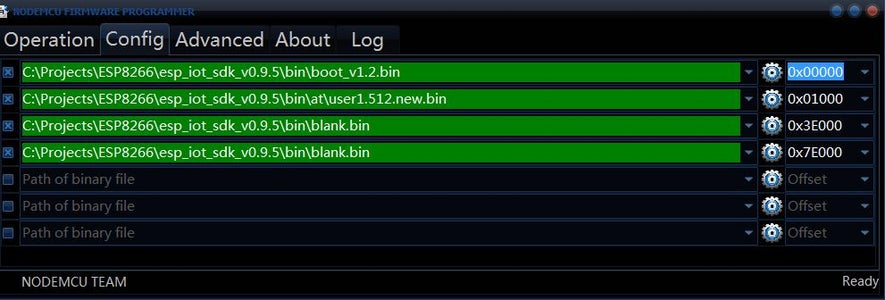
run ESP8266Flasher.exe and select the second tab "Config"
Select from the esp_iot_sdk_v0.9.5 directory 4 files, and change the offset
c:\projects\ESP8266\esp_iot_sdk_v0.9.5\bin\boot_v1.2.bin 0x00000
c:\projects\ESP8266\esp_iot_sdk_v0.9.5\bin\at\user1.512.new.bin 0x01000
c:\projects\ESP8266\esp_iot_sdk_v0.9.5\bin\blank.bin 0x3e000
c:\projects\ESP8266\esp_iot_sdk_v0.9.5\bin\blank.bin 0x7e000
Yes you are right! The blank.bin will be uploaded twice.
Select in the Operation tab the your COM port, (In my example it is COM10).
Do not press flash yet!
Connect GPIO_0 to GND with a wire (or even better, with a resistor).
Reset the device. The device is now in flash mode.
Press the button flash in ESPFlasher and wait until its ready.
Remove the wire from GPIO_0 to GND. And reset the device.
That's it for firmware, let's check!
We are on version 0.9.5. Now, so for sure we should set the baudrate to 115200
Open again the serial monitor (in Arduino) and reset the device.
You will see on the first line some crazy tekst. Don't worry, this is normal. As long as it end with the text "ready".
Send the command AT+GMR and you will have the response:
AT+GMR
AT version:0.21.0.0
SDK version:0.9.5
OK
As you can see, we are on version 0.9.5
Step 3: Setup Toolchain in Windows (the Hardpart)

Let's hope the previous steps were considered as easy.
This will be the hard part.
In Arduino we just press the button "Verify" and the compiler does his work.
Sorry for that. This is not the case for ESP8266. And certainly not for a computer running on windows.
First we have to download the compiler.
The compiler is named xtensa-lx106-elf-141114.7z and can be downloaded from https://drive.google.com/folderview?id=0BzWyTGWIwcYQendHbWlsNUZpX0E&usp=drive_web#list here. It is from a guy named mobyfab. 7z is a zipped file. I used WinZip to extract. Extract this to the directory xtensa-lx106-elf. I use c:\projects\ESP8266\xtensa-lx106-elf for this. (it is compiled for a 64 bit computer, I assume you are running a 64 bit)
Each example has several steps, like building and compiling. Each program has its own script for that. this is called a Makefile. You will find the makefiles in almost every directory Under Linux it is standard peace of software. For Windows we have to install make.exe first.
Download the installer from here https://www.cygwin.com
I have installed, the installer in c:\cygwin\
Run setup-x86.exe and select "make"
Press next until you see the screen select packages. fill in the field "Search" the word "make". (see screenshot)
Expand Devel and select the second last called "Make: The GNU version of the 'make' utility".
It is possible to switch between different versions. (Use the version 4.0-2 the version 4.1-1 could result in a dll error.)
Press next until you are finished.
In other toolchain examples they pointed out to have python. I think it is not needed.
Download esptool.exe, you may find a copy here: https://github.com/JeroenBeemster/ESP8266-Blink
copy this file to c:\cygwin\bin (or the place where you have installed cygwin). A path to this directory has been made by installing cygwin. So we (mis)use this :)
Step 4: Make Blink (compile the Example)

Download the example from github
https://github.com/JeroenBeemster/ESP8266-Blink
Open the file Makefile. (I use Notepad++ for this)
Change the following lines:
XTENSA_TOOLS_ROOT ?= C:/projects/esp8266/xtensa-lx106-elf/bin
SDK_BASE ?= C:/Projects/ESP8266/esp_iot_sdk_v0.9.5
Change these two lines to the place where you have saved the elf-compiler and the SDK in step 3 and 2.
Be aware that the forwardslash (/) must be a forward slash. A a backslash (\) will not work.
Run ESPMake.bat
This batch run's Make.exe that will execute the commands in the Makefile.
Two new directories will be created. These directories are "build" and "firmware".
You may remove these directories, For example, if you would like to re-compile the solution again.
If the following 2 files are created, we have achieved this step.
firmware\0x00000.bin
firmware\0x40000.bin
This is a milestone. If we are here, the next step are easy.
Step 5: Upload the Program to ESP8266

Select the files in the sub-directory \firmware
run ESP8266Flasher.exe and select the second tab "Config"
Select from the firmware directory 2 files, and change the offset
firmware\0x00000.bin
firmware\0x40000.bin
Select in the Operation tab the your COM port, (In my example it is COM10).
Do not press flash yet!
Connect GPIO_0 to GND with a wire (or even better, with a resistor).
Reset the device. The device is now in flash mode.
Press the button flash in ESPFlasher and wait until its ready.
Remove the wire from GPIO_0 to GND. And reset the device.
As you can see these are the same steps as uploading the firmware.
BTW it is not possible to send AT commands to your ESP8266. If you would like to restore to factory settings. Just redo step-2
Step 6: Wiring the Led
Connect the led to GPIO-2 with a resistor (I used 1K resistor).
Connect the resistor to ground.
Connect ESP8266 to a powersource. I use the TTL as the powersource.
There are a lot of information on the internet that warns you to use a powersource that can not deliver enough power. Until now I have not found any problems with this. May be I am just lucky.
Let's hope you are also.
Your led should blink now. We have achieved the goal.
Step 7: Pitfalls / Httpd
1) makefile
Only use forwardslash, never use backslach in makefiles
c:\projects\esp8266 doesn't work
c:/project/esp8266 does.
2) when there is a "find" command in makefile, be aware there is also a windows command named find.
solution is quite simple, add the full path:
change: find
into: c:\cygwin\bin\find
3) I have used cygwin86.exe. It seems that some computers only run on cygwinx86.exe
This file has to be in the bin directory.
4) Example httpd
When you download httpd from github got a library in a subdirectory httpd\lib\heatshrink\ that seems to be empty. Go back to github and download this separate.
5) Example httpd
Trying to compile mkespfsimage c:\cygwin has to be added with the following cgg compiler.


