

Introduction: Brush and Display Together: Camera Lucida for Light Strokes


While Light Strokes let's you paint on the iPad using real brushes and other physical tools, the painting surface isn't on the iPad itself. That makes it difficult to know exactly where your brush is going to end up in your painting when you touch it to that separate surface. This Instructable shows how to build a camera lucida that puts the iPad's display right on the painting surface. That way you can see where you're about to start a stroke, and monitor the digital paint flowing from the actual brush (or other tool) during the course of each stroke, as shown in the video above. This improved feedback allows for much greater control in the Light Strokes painting process (as is taken for granted in both traditional media and touchscreens). If you look at my work on Instagram @rglightsrokes (where I've been posting at least one new painting a day since Jan. 1, 2022), you can see how much more detail I've been able to achieve since adding a camera lucida in mid-February 2022.
There are some excellent camera lucidas on the market, used to assist drawing by superimposing a virtual image of a scene onto a nearby surface where it can be traced. Unfortunately none of those are suitable for this application because:
a. The angle they require between the scene to be drawn and the drawing surface (60° to 90°) is much greater than the 36° angle between the iPad and the Light Strokes painting surface.
b. They're only wide enough for a single eye, since they work with scenes much further away than the tracing surface, which puts their virtual images well below that surface, where binocular vision would only impede tracing. But we'll put the image of the iPad right onto the painting surface, and make the camera lucida wide enough for both eyes to see through it at once, for good depth perception of the approaching brush.
Supplies
- One glass first surface mirror, 6" x 2-3/4" x 1/16" (Boston Craftworks Front Surface Mirror - GLASS)
- One glass 50/50 beamsplitter, 6" x 3" X 5/64" (Two Way Mirrors Teleprompter Mirror 50R/50T)
- Four pieces of carbon fiber tubing, 0.240" O.D.: two 21" long, and two 20" long (TAP Plastics)
- One piece Transparent Bronze acrylic, 7-1/4" x 6-1/2" x 1/8" (TAP Plastics) (and optionally pieces of the same size in other shades such as Lt Smoke and/or Dark Smoke)
- One 5-3/4" long piece of silicone tubing, 1/16" I.D. x 1/8" O.D. (OCS Parts)
- 200 grams PLA (Duramic 3D PLA PLUS)
- A few drops of a flexible adhesive such as E6000 (Eclectic Products E6000 Craft) or silicone sealant (GE Sealants GE5030)
- Eight #8-32 x 1/2" round head machine screws
- Two #8-32 x 3/4" round head machine screws
- Four #8-32 x 3/4" flat head machine screws
- Fourteen #8-32 nuts
- Six #8 flat washers
Other than the usual hand tools you will need:
- 3D printer
- Power drill
- Tools for cutting thin glass (the same as used to cut the mirrors for Light Strokes itself)
Step 1: How It Works


The first diagram shows how the components of the camera lucida are located relative to the Light Strokes hardware, seen from the side. Light rays from the iPad pass through the beamsplitter, are reflected from the mirror, and then from the beamsplitter into the eye. Light rays from the painting surface simply pass through the beamsplitter and directly into the eye, following the same paths as those from corresponding parts of the iPad display after their final reflection.
That's because the axis where the mirror and beamsplitter would meet is equidistant from both the iPad and painting surface. The angle between the beamsplitter and the mirror is 18°, which causes the twice-reflected image of the iPad's display to be rotated about that axis through 2 x 18° = 36°, where it lines up with the painting surface. The mirror and beamsplitter can also pivot together around that axis without affecting that alignment.
The second diagram shows the components that hold the camera lucida at that location. One can easily switch between looking at the virtual image of the iPad on the painting surface, and by slightly raising one's eyes, viewing the iPad directly, over the top of the camera lucida. The camera lucida can also be pivoted around its axis, to provide different viewing positions. In fact, it can be tilted completely out of the way, for an unobstructed view of the painting in progress, again without losing alignment when tilted back into its working position.
Step 2: Make the Parts


All the parts (except fasteners) are shown in the exploded view above.
Cut the first surface mirror to size using the same tools and procedure as in the Light Strokes Instructable. There should have been a large-enough piece left over from that build, but if not, you can order the smaller 12" x 8" piece from Boston Craftworks.
For the beamsplitter, the 5/64" (2 mm) thick 50R/50T Teleprompter Mirror from Two Way Mirrors works well. They can cut it to size, or you can purchase one of their low-cost 6" x 6" samples and cut it in half yourself using the same tools and procedure as for the mirror. Rinse with IPA to remove any cutting oil.
The 3D printed parts, attached here as STL files, can use PLA (as long as they won't be exposed to direct sunlight). Print at a resolution of 0.2 mm, with 15% infill. A heated glass bed coated with hair spray allows the parts to separate easily from the build plate when it cools.
The Cura screenshots show how to place the models for slicing with minimal supports. Be sure to remove any stray bits of PLA from the slots in each of the eight tube clamps that might otherwise prevent them from closing tightly. It can be tricky to remove all the support material from the slot for the first surface mirror in the mirror holder, but it can be pried out with a pick or small screwdriver, or cut out with a knife if necessary.
The carbon tubing may be cut to length (two pieces at 21" and two at 20") with a hacksaw. The cuts do not need to be precise -- those lengths provide enough play for adjustments, and any excess simply extends beyond the printed tube clamps.
The silicone tubing needs to be split to allow it to cover the otherwise exposed edge of the beamsplitter. That can be done with the attached tubing cutter STL, which should be printed flat side down. Thread the tubing through its hole, insert a new #11 X-Acto blade into it, piercing the tubing, then pull the tubing through, and cut off a 5-3/4" piece of the split tubing.


Step 3: Assemble the Parts


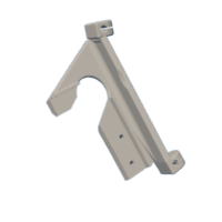
Note that the mirror holder has one solid side (where the first surface mirror will go) and one open side (for the beamsplitter). While the mirror holder is still empty, insert it into the top bracket, solid side first, by aligning its pins with the open slots at the front of the bracket. Angle it in, first inserting the pin on just one side into its hole, as shown in the photo. Then slide the other pin through its slot until it pops into into its hole.
Pull away the protective film about 1/4" from each of the shorter sides of the first surface mirror, leaving it in place in the middle. Slide the mirror into its slot, with its glass (non-mirrored) side against the solid side of the mirror holder, and the mirrored (partially protected) side out. Slide it in until its top edge is just below the adjacent edge of that solid side of the mirror holder. There's an extra 1/8" of space at the bottom of the slot, in case the mirror was cut slightly oversize. If the mirror fits loosely enough that it might slide down farther, the remaining space in its slot can be filled with with a flexible adhesive such as silicone sealant or E6000. Now remove the rest of the protective film from that mirror.
Orient the beamsplitter with its reflective side facing the front surface mirror. (You can tell it from the back side because the later shows the edge of the glass clearly, as well as a gap between a fingernail touched to the glass and its reflection, as in the photo above.) Slide it into its slot, holding it from the edges to avoid getting fingerprints on it. The slot is 1/2" deeper than the 3" height of the mirror, because its preferred height depends somewhat on the desired viewing position. Try it first at a position 1/4" below the top of its slot, with 1/4" pieces of cardboard in the bottom of the slot to hold it in place there. Once you find a beamsplitter height that works for your viewing position, you can fill any remaining space in the slot below it with flexible adhesive.
The split silicone tubing is used to cover the sharp edge of the beamspliter. Spread it open at one end and place it over of the top edge of the beamsplitter at one side. Then press the rest of the length of tubing onto that edge. It can be held in place at both ends with a bit of flexible adhesive.
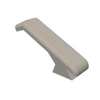
Snap the left and right caps into the sides of the mirror holder, to keep the mirror and beamsplitter from falling out when the mirror holder is tilted upside down.
You can rotate the camera lucida within the top bracket by pressing in on the tops of the handles on both sides that otherwise clamp it into position. For now, rotate it to its default position, where there's a detent.
Next you'll need to attach the left and right brackets to Light Strokes' iPad supports. For the one on the left, first temporarily remove the top mirror baffle (held in by six screws, including the one from the front, next to the camera opening). Clamp the left bracket to the left iPad support, with its top and side guides firmly against the edges of the iPad support, and without covering the holes in the bracket. With a #18 bit, drill two holes through the iPad support, using the holes in the bracket as a guide. You can now replace the top mirror baffle, and clamping the right bracket to the right iPad support, drill two holes through it in the same way.
Slightly countersink those four holes on the front side of the iPad supports. (You shouldn't remove too much material from the partially infilled print, and it's OK if the flathead screws compress it somewhat and still protrude slightly, since the rubber pads on the iPad support provide almost 2 mm clearance to the iPad itself.) Insert a #8-3/4" flathead screw into each of those holes and fasten the brackets to the iPad support with #8 flat washers and nuts. These two brackets provide the sole support for the camera lucida, so make sure they're fastened tight.
Insert #8 nuts into each of the ten recesses for them in the three brackets. Thread a #8-1/2" roundhead screw into each of the eight tube clamps. Thread two #8-3/4" roundhead screws with flat washers into the two nuts for the filter holder at the base of the top bracket. Keep all of those loose for now.
Insert the 21" carbon fiber tubes into the upper tube clamps on the left and right brackets, and then into the upper clamps on the top bracket, with the beamsplitter facing towards the iPad supports. With the tubing extending 3/4" beyond the back of the clamps on the top bracket, tighten the screws in those clamps. Leaving 17-3/4" of exposed tubing between the clamps, tighten the screws in the upper clamps on the left and right brackets.
Thread the 20" tubes through the lower clamps on the brackets, again leaving 3/4" of tubing extended beyond the back of the clamps on the upper bracket before tightening those clamps. Now leaving 16-7/8" of tubing exposed between the clamps, tighten those on the left and right brackets. Note that that's greater than their relaxed length, putting the top tubes under tension, which makes the assembly less prone to vibration.
The completely assembled camera lucida is shown in the last photo.
Step 4: Calibration
This video shows the new calibration procedure (in the Light Strokes app v.3.0 and later). It's much easier than the old procedure, but you'll still need the wettable printed test pattern from steps 7 and 9 of the Light Strokes Instructable. Here is the new procedure:
- Wet the test pattern and place it face down on the wet painting surface. Center the test pattern on the glass (3/4" in from each edge) and make sure it's square with respect to the edge of the glass.
- With the iPad in place and the LEDs on, open the Light Strokes app and go to the settings panel. Select Default Settings and then Get Defaults, to undo any changes you've made to them.
- Open the settings panel again, select Show Video, turn on Preprocess, and touch Autofocus: Once. Then select Calibrate.
- The popup explains what to do next, select OK to dismiss it. Adjust the settings as needed for a clear image of the dashed rectangle in the test pattern (here I only needed to increase the ISO slightly). Zoom in or out until you can just see all four corners of the sheet on which the test pattern is printed. Then select Continue Calibration.
- Again, the popup describes what to do next, and you can select OK to dismiss it. Drag the red lines by their corners to line them up with the image of the dashed rectangle. Use the stepper (+/-) controls to make fine adjustments to any of the X and Y coordinates of the corners. Once they're all aligned, select Save New Calibration to complete the procedure.
Next you'll need to align the iPad's video image of the printed test pattern with the physical test pattern itself, when viewing them together through the camera lucida. To do that, leave the printed test pattern in place on the painting surface and keep Show Video selected.
Step 5: Alignment


In order to be able to look through the camera lucida from a comfortable position, you may want to place Light Strokes on a slightly lower table. It also helps to tilt the whole unit forward, by putting a block underneath it near its back. Using a block about 1-1/2" tall, tilting it forward by about 10°, works well for me. Just make sure you don't tilt it so far forward that the iPad no longer rests against its supports.
When you look through the camera lucida, you should see something like the first photo above (in which the black blobs are air bubbles under the test pattern). The virtual image of the iPad is superimposed on the view of the painting surface, but they're offset from each other. I reduced the ISO and Exposure to make the iPad's image darker, so that the printed pattern on the painting surface can be seen more clearly.
If you move from side to side (or close one eye and then the other) you'll probably see some parallax between the vertical lines in the two images, indicating that they are at slightly different depths. Whichever one tends to follow your eye is at the greater depth. You can see that in the video here, particularly near the left edge, where the lines in the printed test pattern tend to follow the movement of the camera (which begins with a move to the left), indicating that it is slightly below the virtual image of the iPad.
To lower the image of the iPad to the same plane as the painting surface, the camera lucida itself must be lowered. Likewise if the virtual image needed to be raised higher, the camera lucida would also need to be raised. This is best done by first moving the top bracket manually to find where the alignment is improved. Then loosen one of its tube clamps slightly, in order to move it closer to that better position, re-tighten it, and repeat as needed with the other clamps on the top bracket. Of course, the bracket will move somewhat when you let go of it, so this is an iterative process. While making these adjustments, it's also important to keep the horizontal edges of the iPad screen parallel with horizontal lines on the print, most readily verified by showing the menu bar. You'll also want to keep the center of the the virtual image of the test pattern close to the center of the print, ideally within about 1/4" in both X and Y. The second photo shows how my system looked after completing this mechanical part of the alignment. To get there, I ended up reducing the length between the clamps for the lower tubes on both sides by about 3/16", but leaving the upper tubes at their original positions. You may well need to make different changes, but they should only need to be of about that magnitude.
Once you've got the virtual image in the same plane as the painting surface, open the settings panel and adjust the X and Y offsets to line up the iPad's image of the center of the test pattern with its actual center on the painting surface. Then adjust the X and Y scales to line up all the horizontal and vertical lines. When you're done, you should have something like what's shown in the third photo, and with little or no parallax as you look through each eye. In my case, these were the final settings to get there:
- X offset -0.05
- Y offset 0.25
- X scale 0.22
- Y scale 0.27
Again, I would not expect those to be the exact settings you'll need, but they indicate the approximate magnitude.
When you remove your iPad from Light Strokes and later replace it again, you'll probably need to do a bit of realignment, as it's unlikely the iPad will return to the exact same position. Typically, you'll only need to readjust the X (and possibly Y) offset, and you can do that without using the test pattern, by simply spraying some glass cleaner on the painting surface, leaving bits of foam distributed over it, as shown in the last photo above. Then on the settings panel, select Show Video and adjust the offsets to line up the video image with the actual bubbles. For the X offset, you can often simply nudge the IPad itself slightly to the left or right to get it back to its original alignment position. You can further check the alignment with a small thin brush touched to various positions on the painting surface. If you find that it's aligned in the center but offset in opposite directions at the extremes, then you would need to also readjust the X and/or Y scales. Of course you're free to use the test pattern for this purpose as well, and as long as you're only realigning the camera lucida and not doing another calibration of Light Strokes itself, you don't need to worry about getting the test pattern exactly centered or square.
Step 6: Add Filter


Since the light from the iPad display passes through the beamsplitter as well as being reflected from it, its virtual image retains only about a quarter of its original brightness. By contrast, the light from the painting surface just passes through it once, cutting its brightness only about in half. That means that when the painting-in-progress (or a part of it that you're working on) is dark, the light from the painting surface can be overwhelming. For this reason, a filter can be used to reduce the light from the painting surface, making the painting appear relatively brighter.
The filter is simply a piece of 1/8" translucent acrylic, cut as shown in the diagram. If you don't have a laser cutter, you can 3D print the attached drill guide (flat side down) and use it to position a 1/4" drill bit at the right locations.
The filter then slides into the bottom of the camera lucida holder, till its holes are engaged by the pins there, as shown in the photo. The angle of the filter should then be adjusted by tightening the two screws at the bottom of the holder until the filter completely encompasses the virtual image of the iPad display, all the way to its top. But if it starts to encroach on the bottom of the iPad display, then you've gone too far and will need to loosen those screws to lower it a bit. Once it's in position, it's easy to remove the filter, for cleaning or swapping in different ones, by simply lifting it out, without adjusting the screws. Likewise, no further readjustment should be needed when a filter is re-inserted. You might find that you need to adjust it slightly if you tilt the camera lucida to a different viewing position, but you should be able to find a single filter angle that works for all your viewing positions.
When the painting contains mostly bright colors, either no filter or only a fairly transparent filter (e.g. Transparent Lt Smoke, 57% transmittance) may be needed, and a filter that's too dark will make brushes difficult to see. But when and where the painting is darker, light from the painting surface can be overwhelming, and a darker filter (e.g. Transparent Dark Smoke, 36% transmittance) may be needed to see the painting clearly. I've found that the Transparent Bronze (47% transmittance) provides a good filter for most paintings. All four of those cases are shown in the final photo, for brushes on pure black and pure white regions of the painting. Note that the filters only change the brightness of the brushes and painting surface, not that of the painting, since the light from the iPad doesn't pass through it.
Attachments

Step 7: Using the Camera Lucida


Once you have the Light Strokes hardware at a height and tilt that allows you to easily view its painting surface through the camera lucida, you may find that you can get a better view of the overlaid display image if you adjust the angle of the camera lucida itself. To do that, squeeze in the tops of its side handles so that it is free to rotate and tilt it to a more comfortable or complete view, and then release the handles to let it stay there.
Similarly, you can temporarily tilt the camera lucida forward or back far enough to provide an unobstructed direct view of the iPad. This is good for checking your work without the light from the painting surface being mixed in. Then when you want to resume using the camera lucida, simply squeeze its handles and rotate it back into position.
I hope you enjoy using the camera lucida with Light Strokes, and I'd love to see the kind of detailed work you do with it if you'd care to share any. Again, you can see what I've done with it, since mid-February 2022, on my Instagram feed @rglightstrokes. A few examples of those, that I could not have painted without the camera lucida, are shown above.

Runner Up in the
Build a Tool Contest


