

Introduction: DogBot V2.0: Design Your Own Quadruped Robot (Part 1)


Hey all!
This is a step-by-step guide of designing a four-legged robot, also known as a Quadruped, using Computer Aided design tools. The design of the quadruped is inspired by Boston Dynamic's Spot robot and looks somewhat like a dog. The bot is designed for additive manufacturing and can be easily 3D printed using any commercial FDM/FFF printer. Though, I plan on physically making the robot, this Instructable will only cover the designing phase of the project. I will be soon posting the step-by-step process of fabricated the quadruped too.
I will go through the entire generalized design process of the robot, so you do not necessarily have to replicate what I am building. Using the Instructable, you can get as creative as you want and create any legged robot. I will also touch upon the tools used for photo-realistic and contextual rendering.
Hope you enjoy reading it and do post your designs in the comments!
Supplies
For the designing phase, not a lot of supplies are needed. I mainly used:
- SolidWorks (designing)
- Visualize (Rendering)
- Desktop/Laptop
- Computer mouse (Not necessary but suggested. Makes the job much easier)
Step 1: Sketching the Concept


The first step of designing process is to take out your sketch books and start sketching different concepts of robots. The sketches do not have to be perfect, just needs to have the general shape and form of the components with some rough estimated dimensions. I started off with very rudimentary 2D sketch concepts, as shown in the images, with the basic outline of the robots and limb dimensions. After I had the preliminary ideas, I finalized upon the dog inspired robot with a parallel driving mechanism for the lower leg. Then, I got into more details like the placement of electronics, the kinematics of the legs and the leg driving mechanism etc. I have also shown some of the rough sketches which I used to ideate the components in detail.
For the detailed drawings, I would suggest sketching in 3D for better visualization of the design. Here are some resources for product design sketching:
- TheSketchMonkey's "3 Important Sketching Exercises for Any Designer (Beginner) - YouTube"
- Sketch a Day's "Sketch-A-Day - How to sketch complex organic shapes - YouTube"
- Reid Schlegel's "Sketching Basics 2: Perspective is King - YouTube"
Along with detailed 3D drawings, I would also encourage you to draw rough sketches of the components just to ideate better.
Step 2: Importing/Downloading Electronics
Considering electronic components while designing the bot is an important part of any robot design process. Designing each electronic component can get tedious, so I sourced most of the electronic components from GrabCAD (Popular models | 3D CAD Model Collection | GrabCAD Community Library). Solidworks allows users to directly import pre-designed electronic components to assemblies like servos, batteries, controllers etc in .STEP, .SLDPRT .STL, etc. file formats. Files in unsupported file formats can be converted to .STEP or .SLDPRT using any online free converters.
Here is a list of electronics which I imported from Grabcad:
- Servos: Lewansoul LX-16A bus servo | 3D CAD Model Library | GrabCAD
- DC-DC buck Converter: DROK Adjustable DC Buck Converter Model 180078/180080 with built in mount | 3D CAD Model Library | GrabCAD
- Servo Bus Linker: LewanSoul LX-16A Servo Bus Linker | 3D CAD Model Library | GrabCAD
- Battery: TalentCell Rechargeable 12V 3000mAh Lithium Ion Battery Pack | 3D CAD Model Library | GrabCAD
I could not find the CAD of libre computer (Le Potato) online, so I made it myself. It can be found here:
Le potato: AML-S905X-CC (Le Potato) | 3D CAD Model Library | GrabCAD
STL files for the robot can be found here
Step 3: Designing the Upper Leg


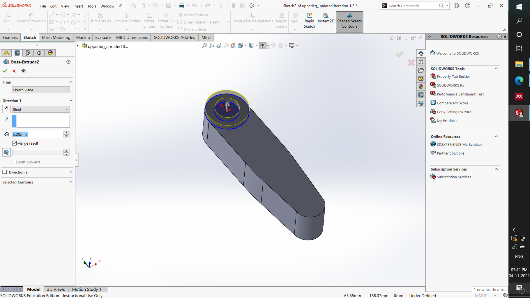


We are all set now, let us begin designing the quadruped robot!
To design the upper leg, I started off with basic sketch shown in image 1. The sketch was extruded to a thickness of 30 mm. Post that, interface for the primary motor shaft was extruded and holes for M2 x 8 machine screws were created to mount the motor connector. This connector is the interface between the motor shaft and the upper leg. After the basic form of the upper leg was ready, I cut out 45x18 mm slot for the secondary motor and 50x18 slot for the lower leg mounting. Following this, other finer details like slots for cable management, secondary motor supports and finishing touches were added the CAD model.
Step 4: Designing the Lower Leg


To design the lower leg, I followed a similar process. First, I created a basic sketch inspired from the rough sketch concepts in step 1. Post that, I extruded the sketch and added finer details like the holes for the barrel screw, slot for the parallel linkage mechanism and the modular toe cut out.
Step 5: Assembling the Leg


In this step, the two parts of the leg will be assembled together, and the motor 2 will be attached to upper leg. For this, we need to open all three components in the workspace and mate them as per the design. Once the upper leg, lower leg and the motors were assembled, the compliance linkage and the servo horn were modelled and added to the assembly. We are now done with designing the legs. Let us move to designing the chassis now!
Step 6: Chassis Assembly


In this step, all the components of the robot chassis will be put together. This includes electronics and the power source.
Step 7: Putting It All Together and Finishing


Once all of these components are ready, we put them together and we have our quadruped ready!
To generate high quality renders and finish the robot, I used Visualize.
Thanks for reading!

Participated in the
Teach With Tinkercad Contest


