

Introduction: Build a Robotic Remote Controller


In this post I will describe how I design, make, test and improve a customized RC remote controller.
The goal of this project is to create a remote controller that can be alternative to a RC transmitter or similar commercial controllers. The remote controller we build would be able to control, manipulate our robots, flying planes like quadcopter, even can be used for PC gaming like car racing games, but I would leave that in the future.
This project requires good understanding of programming in Arduino. I will be using the Ciesco XRF module for wireless communication, but you can also use XBee moduels.
I am trying to keep this instructable simple yet clear. If you want more detail or have any question, please refer to my detail project log:
Part 1: https://oscarliang.com/diy-wireless-rc-remote-controller-for-robots/
Part2: https://oscarliang.com/robotic-remote-controller-protocol-design/
Let's take a look what it can do.
After watching this video, you might be wondering how to build this robot too. But this is a whole separate project. I might write a instructable for this. But for now, refer to my quadruped robot project page for it.
To demonstrate what each control component can do, take a look at this demo video.
Step 1: Planning and Design


First of all, draw your desired design on paper. Make usre you measure each component, and leave enough space bewteen them. Also make sure they are not too close to affect user experience.
What components to use is largely dependant on what kind of project or robot you are trying to control. For example for a simple robotic tank, you might want to be able to make it go forward and backward, turn left and right. So four push buttons would be enough to accomplish this.
For my remote controller, I am not designing it narrowly for some particular projects, but for more general usage. Therefore I used a combination of different types of control components.
Here are the parts I used:
- Toggle Switch x 4
- 2-Axis Joystick x 2
- Potentio Meter x 4
- Push Button x 6
- LED x 3
- LCD x 1
- Arduino Mega x 1
- Cables x many
- Small Breadboard x 2
- Ciesco XRF Wireless Modules x 2
After that, I connect the component on a breadboard, and test them.
Step 2: Preparing Components


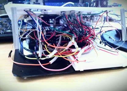
I try to keep soldering to the minimal, so I use a lot of jumper wires.
Make sure you have all sorts of jumper cables ready: Female to male, male to male and female to female. And make sure they are long enough, generally you want them to be twice as long as the width of your remote controller, so you can have the panel and base laid down naturally side by side while you are connecting the components. Otherwise you will have a really painful time doing that. For trouble shooting, it’s even worse when short cables are used.
The wiring could be real messy, so make sure you use different colour cables, to help you identify them.
Step 3: Programming


Software for this project consists two parts, one for the remote controller (which I call “Host” later on), and the other for the robot (“Client”).
The programming on the remote controller has a flow chart shown on the first image. It is responsible for initializing connection, re-establishing broken connection, encoding commands and provide feedback from client to the user. There will also be a LCD menu system to provide current state information of the controller, allow real time parameter adjustment, calibration and so on.
Second picture is the flow chart for the client. It is responsible for accepting connection, decoding commands and communicating back.
Communication
As for sending data, because we are using the serial pins on the Arduino, I will be using Serial.write() for sending data. This function sends one byte of data which means the max value we can transmit is 255 each time we call this function.
You might be wondering what we should do about the inputs from the potentiometers and joysticks, as they have a max value of 1023. We have two options, one is to downgrade resolution to map the value between 0 and 1023 to a new value between 0 and 255, which can be fit in one byte. Second option is to treat the number in term of bits (1024 can be represented with 10 bits), which can be send separately as two packets. When they arrived at the client side, we put them back together as one number. As you might know, for a single value, sending two bytes would take longer than one byte. Although it’s less accurate, we sometimes don’t need that level of accuracy and prefer smaller latency. So I am planning to adopt both methods into the remote controller communication, so user can select which way to go depends on the situation.
Link to the Source file can be found on the project log. Like I mentioned, you need to know how to use Arduino to use the source code.
Step 4: That's It! Some Improvements


By now, you should have a working Remote controller, it's not essential, but there are still room for improvements. I made a few improvements in the programming, for detail you can find in this post.
Second picture shows one of the improvement, how having a input buffer array can smooth out the output.

Participated in the
Remote Control Contest

Participated in the
Home Technology Contest


