

Introduction: Build Your Own 3d Printer Filament Factory (Filament Extruder)


Too long, didn't read:
Make your own 3D printer filament !
Cheap and high quality at a decent speed of 150-190 IPM ! (4-5 meters per minute)
UPDATE: Now with wiring diagram !
Long read:
3D printers are cool and they finally start to drop in price. Kickstarter campaigns like the one from QB-UP or M3D are popping up and they are finally "affordable". And with affordable I mean affordable like 200 $ and not "affordable" like 2.199$ affordable. However, once you are a proud owner of a 3D printer you will soon realize that your wallet is far from being let alone. No ! You need plastic filament of course to print those super awesome coat hooks and wheel chocks. Since the price for these filaments tend to top the actual material costs, printing before mentioned life savers is kind of expensive and could become a problem to the development of the ever growing 3D printer community
BUT FEAR NO MORE !! Some clever gents came along - Hugh Lyman with his Lyman Extruder may be mentioned here or the guys over at Filastruder.com - and saved the day ! YAY. And there was much rejoicing ! They have built plastic extruders everyone can build or buy at a decent price. However if you are a fellow Instructable.com user the first thing that should come to your mind is "I can build this by myself...and cheaper...". Building at lower costs is the nature of DIY after all.
And much more fun than putting together a premade kit, of course.
Special greetings go out to Xabbax and his plain simple but super awesome Low Cost Filament Extruder !
So how much money do I save when making my own filament ?
Good question ! A lot !
Depending on the pellets you get you can make your filament starting at 1$/kg.
How long does it take to produce 1 kg of filament you may ask ??
Using the build I describe here...roughly 1 hour. (for 1,75mm filament using ABS/PC pellets).
So, let's say on a Saturday in your next workshop session you start at 10 AM and batten down the hatches at 5 PM you could make 4-5 kg of filament, saving between 125-150 $ leaving you with lots of filament for hundreds of thousands of eggcups and phone cases and other useless needful things.
Oh yeah what about the build cost ?
Depending on shipping and local prices, I would guess around 130-150$.
Next step: List of Materials
Step 1: Material List
Except for the electronics everything listed here can be bought at your local hardware store.
Materials:
- 1x Wiper Motor (Ebay EU - 15€) / 5€ from the junkyard
- 1x Auger bit(diameter = 16mm ; length = 460mm)
- 1x PID Temperatur Controller - DC 12V version (Ebay)
- 1x SSR-25DA Solid State Relay 3-32V DC / 24-380V AC / 25A (Ebay)
1x K-type thermocouple (Ebay - like this one; does not need to be that shop :) just an example)
-->!!! Sometimes the PID is bundled with an SSR and an K-Type Thermocouple !!!<--- 1x Motor Controller 20A (Ebay)
- 1x Power Supply 12V, 240W+ (Ebay)
- 1x Heating band (200 Watt 25mmx30mm) (Ebay)
- 2x Fans (80mm) 12V
- 1x Fitting 3/4" US Inch UNC --- 1/2" German Inch - 18cm long
- 1x Water tap extension - 3/4" UNC threads --- 1/2" German Inch - 50mm long, 27mm diameter (one core thread and one exterior thread)
- 1x End cap 1/2"
- 1x Faucet-mounted filter - 1/2" diameter
- 3x Steel angle
- 1x Axial ball thrust bearing (Ebay) - Fitting exactly onto the auger bit's shaft.
- 2x 10mm threaded rod
- 1x Insulation
- PTFE tape
- Heat resistant tape
- 3x Rocker (previously "rocket") switches
- 1x Wooden board 100cm x 10cm x 2cm
- Several screws and nuts
- 2x sockets (1 that fits on the auger bit and 1 that fits on the nuts of the motor shaft)
- Wires (two colors)
Tools:
- Multitool (Dremel-like)
- Saw
- Hammer
- Drill
Step 2: Base Plate


Take the wooden board and cut away two pieces each 15cm in length (~6"). They will serve as a mount for the motor and for the barrel.
Step 3: The Motor Mount


Mount the wiper motor to the motor mount and place it somewhere at the end of the base plate. See the technical drawing for an estimation.
Use the steel angles to attach it to the base plate.
The motor just has a threaded shaft. For the coupling to fit onto the motor I took a hex-nut with 13mm outer diameter and put it on the shaft. When the shaft rotates and the coupling is attached, the nut would untwist. To fix this I drilled a hole in-between the attached nut and the motor shaft and put in a 2mm steel bolt. This prevents the nut from opening. See the last picture above.
Step 4: The Barrel Mount


Drill two holes into the other piece of wood so the flanges can be attached left and right of the board. Drill another 1/2" hole for the auger bit.
Both mounting boards need their center opening to be aligned to each other so the auger / coupling / shaft-axis can rotate freely.
Fasten the flanges with two pieces of the 10mm threaded rod. The rods must be left long enough so they can be screwed to the auger "kickback protection". 10 cm is good enough. They can be cut to size later on.
This will get clear in the next step.
Step 5: Auger Kickback Protection


When the auger bit turns and hauls the pellets a lot of pressure builds up. In the worst case this could damage the worm drive inside the wiper motor. To counter that problem, we need a kickback protection. This is simply done by a sturdy steel angle and an axial ball thrust bearing.These ball bearing withstand alot of force applied to them.
It works like that: The auger pushed back due to its "backward" turning attitude. Because of its taper the auger's shaft pushes against the axial ballthrust bearing which itself pushes against the steel angle. The coupling between the auger and the motor should always have a little clearance. So that no force is applied to the motors shaft.
Now place the steel angle with the inserted rods at a distance to the barrel mount so that the auger's shaft sticks out for about 3-4cm (~1.5"-2").
The pictures should explain it as well. Moreover I have made a short video that should illustrate it as well. The dimensions of the parts might differ from the ones you have access to. So exact measurement might not help you very much, but the pictures should give you an idea how it should be put together.
Step 6: The Barrel and Auger Bit


Barrel:
Smooth out the ends and the seams of the pipe so the auger bit can rotate freely.
Before cutting an opening into the pipe screw it tight onto the flange and mark the upper area and remove the barrel again.
Take your multitool and cut out the marked area at the end of the pipe where the pellets should fall in. Wind some PTFE tape around that end of the pipe. This should prevent the pipe from turning with the augers movement. Remember the motor is very powerful and if there is some friction between the auger and the pellets, the pipe easily turns another 4-5 mm even if it was fastened with a monkey wrench.
The threads on the flange and fittings are not made for perfect 90° angles. So the fitting/barrel might stand in an oblique angle. To fix this take some washers and place them under the flang where necessary.
Take a square piece of wood and drill a hole lengthways for the pipe to run through. Now drill another hole orthogonal to the "pipe channel" so that a bottle can fit tightly. Now just cut the block in half for easy dis/-assembly.
Auger-bit:
The auger might be too long so you need to cut off its tip with an angle grinder.
The auger bit should reach up to the heater. See the pictures above.
Step 7: The Auger-motor Coupling


Take a 5cm (2 inch) piece of a square steel that fits into the ends of the sockets (about 12mm edge length).
Put the coupling on the auger bit and attach the motor to the motor mount.
The coupling should now fit nicely in-between.
Alternatively you could use a spark plug socket instead of the two sockets. But therefore the distance between the motor-mount and the auger/barrel-mount needs adjustment.
I went with the above mentioned method because I did not have spark plug socket at hand but I will try this with the next build.
Step 8: The Nozzle


Nozzle diameter:
Depending on the material you process the diameter of the hole in the nozzle will vary and finding the right dimension is a process of trial and error. For ABS/PC blend pellets with a melting point between 240-280°C a 1.5mm hole perfomed well from my experience.
Breaker plate:
Take the faucet-mounted filter and cut it into a 1/2" diameter if needed. This will act as a breaker plate. What this breaker plates does is mix the molten plastic and retains dirty (which should not be there of course) and eventually small bubbles that could occur in the melting process. This helps smoothing the plastic pushing through the nozzle.
Be sure there are no chippings or strands ! You don't want to ruin your printers nozzle !
Take a washer, place it inside the end cap and put the DIY breaker plate on top.
Step 9: Band Heater and Temperatur Probe (K-type Thermocouple)


Drill a 2mm hole near the front of the water tap extender for the thermocouple to fit in.
Strip the thermocouple wire to length. It should just be as long as needed.
Push the band heater on the tap extender. It should sit around the end of the extender.
Next take some PTFE tape and wind it around the thread of the tap extender. This prevents the molten plastic from squeezing through the thread.
Fix the thermocouple with some heat resistant tape.
Then put on the nozzle from the previous step.
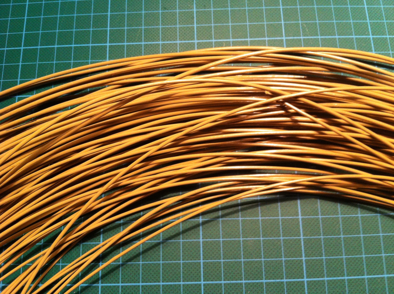
Next, take a 10cm long piece of aluminium tubing with a diameter of around 1cm and place it in front of the nozzle using some rigid wire. This gives the filament a nice curl when cooling.
Thanks Xabbax for the idea.
Now wrap the insulation around the heater so that the nozzle is covered as well.
Step 10: Cooling


The front of the nozzle and the motor needs some cooling.
The filament is still very hot and soft when it exits the nozzle. To prevent it from stretching too much from the affecting g-forces when falling down, cooling is very important. The more you cool the better you can control the diameter of the filament later on.
Although the motor builds up some heat and the fan helps to keep it cool.
Step 11: Electronics


Now that most of the mechanical parts are set and done it is time for installing the electronics.
But before, take a piece of wood for the front enclosure and arrange the 3 rocket switches, the PID controller and the motor controller's potentiometer and fix them with some hot glue.
Main power
Connect the power cord via a rocker/t switch to the power supply (Ports L, N and Ground).
PID temperature controller
Connect the PID temperature controller via rocker switches to the power supply.
Solid State Relay & Band heater
Connect the 12V ports of Solid State Relay to the PID (Port 6 and 8)
Connect port 1 of the SSR to the 220V (EU) /120V (US) port (Port L) of the power supply.
Connect port 2 of the SSR to one of the band heater ports.
The other free port of the band heater is connected to the N port of the power supply.
What does the SSR do actually ??
The band heater is a 220V part but the PID only runs on 12V. Therefore the SSR connects the 12V PID with the 220V heater. The PID powers the SSR on and off if needed. When it is on then 220V are connected to the band heater and it gets warm. If the relay is off, the band heaters isn't connected to 220V and ergo is powered down. The idea is to control a high power device (Heater) with a low power device (PID).
Motor controller
Connect the motor controller via a rocker switch to the power supply. Then connect the motor to the motor controller. Use the pinout for the 2nd speed setting of the motor. The pinouts differ from model to model and you first have to find out which pins are for which speed setting.
The two fans are connected to the same ports as the motor is to the motor controller.
Wiring diagram
I am not sure if I am allowed to post the wiring diagrams for license reasons so I will link to the respective websites.
2) Filabot Wee wiring diagram (scroll down)
3) Here is a link to the Sestos PID I used.
Step 12: Extrusion Settings and Setting Up the PID


Different materials need different extrusion settings.
For pure ABS a temperatur of 190°C is about right.
PLA requires less heat and ABS/PC blend needs higher temperatures like 260-270°C.
The Sestos PID is able to autotune to the desired temperature.
PID controller setup:
To enable the autotune function press "SET" for 3 seconds.
You will now see "HIAL" on the display. Now use the DOWN button until you see "Ctrl" and adjust it to "2". This is the number for the autotune function. Press "SET" again until you see the temperature readout again. Just after all the EP1-8 options. Set the desired temperature using the up and down buttons and wait until the display stops flashing (~10-15 minutes).
Activate the motor and let the extruding begin. You have to play around with the speed of the motor.
From my experience setting the potentiometer to half speed @ 270°C for ABS/PC performed very well.

Third Prize in the
Full Spectrum Laser Contest


