Introduction: Building a Wireless Soil Moisture Sensor With ESPHome and Home Assistant


In this Instructable I'll guide you on how I build a wireless soil moisture sensor system using the ESP8266 ESP-07 module and integrate it with Home Assistant through ESPHome. This project is perfect for anyone looking to optimize their garden irrigation system by automating watering based on soil moisture levels. Not only will it help in conserving water, but it will also ensure that your plants get the right amount of moisture they need to thrive.
In this tutorial, I will guide you through each step of the process, from setting up the hardware, configuring the software, to packaging the sensor for use in your garden. I'll be using accessible and cost-effective components, making this project ideal for both beginners and experienced enthusiasts. You'll need a few basic electronic tools and some programming knowledge, specifically with Arduino and ESPHome, but I'll make sure to keep the explanations simple and easy to follow.
The project is sponsored by PCBWay. They have an awesome shared projects library that you can use for inspiration and you can order any of them.
Supplies

Tools and materials used in the video:
- ESP8266 ESP07 Module - https://s.click.aliexpress.com/e/_onPzbBs
- Capacitive Soil Moisture Sensor - https://s.click.aliexpress.com/e/_m0WA2LU
- Sensor with ESP32 Module combo - https://s.click.aliexpress.com/e/_DmHGbxv
- TP4056 Battery Protection and Charging module - https://s.click.aliexpress.com/e/_EHuFTVz
- USB to Serial adapter - https://s.click.aliexpress.com/e/_oCHEON0
- Jumper Wires - https://s.click.aliexpress.com/e/_mtHfcPy
- Mini Breadboards - https://s.click.aliexpress.com/e/_on0J3Z8
- Mini PC for Home Assistant - https://s.click.aliexpress.com/e/_okQPKRy
- Soldering Rework Station - https://s.click.aliexpress.com/e/_m00zmaw
- Multimeter - https://s.click.aliexpress.com/e/_m0CIYDY
- Wire Snips - https://s.click.aliexpress.com/e/_omwVb18
- ESD Safe Tweezers - https://s.click.aliexpress.com/e/_ol7L3Ma
Step 1: Understanding Your Components


Let's begin by familiarizing ourselves with the main components needed for this project: the ESP8266 ESP-07 module and the capacitive soil moisture sensor. The ESP-07 is a versatile, Wi-Fi-capable module based on the ESP8266 chip, ideal for IoT projects due to its compact size and low power consumption. It's smaller than a typical NodeMCU board but powerful enough to handle our requirements for wireless communication.
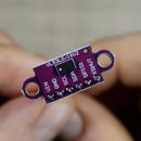
The capacitive soil moisture sensor is key to measuring the moisture level in the soil. Unlike resistive sensors, capacitive sensors don’t corrode over time, making them more durable and reliable for long-term use in a garden environment. This sensor outputs an analog signal that varies depending on the moisture level, which we'll read through the ESP-07 module.
For connecting to our Home Assistant smart home server, we'll use ESPHome, a system that allows creation and management of custom firmware for ESP8266 and ESP32 devices. ESPHome seamlessly integrates with Home Assistant, providing a straightforward path to add our sensor into the overall smart home system. Using ESPHome, we can program the ESP-07 to send soil moisture data over Wi-Fi to Home Assistant, where we can monitor it or use it to trigger events like turning on a sprinkler system.
In my case, I will be controlling my DIY irrigation controller which you can check out here.
Step 2: Preparing Flashing the ESP 07 Module


Before we can start utilizing the ESP-07 module for our project, we need to first prepare it for flashing with the ESPHome firmware. This involves setting up the appropriate connections so the module can communicate with our computer for program uploads.
You will need a USB to serial converter that operates at 3.3 volts, as ESP-07 modules are not 5V tolerant, and using a higher voltage could damage the device. Make sure your converter can also handle the communication logic at 3.3V.
Using a breadboard can simplify the process of connection as we need to have multiple connections from VCC and GND.
. Here's how you should wire it:
- Connect the VCC pin of the ESP-07 to the 3.3V output on the converter.
- Connect the GND (Ground) pin of the ESP to the GND on the converter.
- Connect GPIO15 to GND.
- The ESP module’s TX (transmit) pin should connect to the RX (receive) pin on the converter, and the RX pin to the TX pin. This cross-connection is necessary for proper data transfer.
- To enable flashing mode, connect the GPIO0 to GND. This setup needs to be done only when you intend to flash the module. Remove this connection for normal operation.
- Finally, the EN (Enable) pin should be tied to VCC to ensure the module is active during the flashing process.
When you power up the module, ensure that GPIO0 is grounded. This will put the module into flashing mode, indicated typically by a specific pattern or lack of LED activity, depending on your module’s design.
Once the device is in flashing mode, we can either use Arduino IDE to load a specific sketch like Blink for example or as in my case, I used the web installer of ESPHome to install the device with an empty firmware so I can adopt it in Home Assistant.
Step 3: Removing the Power LED (Optional)

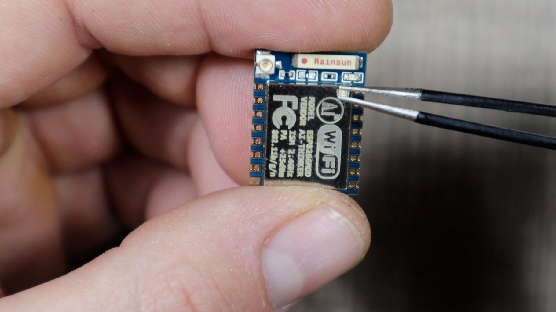
Now that our ESP-07 module is set up and the firmware is flashed, we need to focus on optimizing the system for battery operation. One of the tweaks to enhance battery life is removing the power indicator LED. LEDs, while useful for debugging, consume power unnecessarily when we move the project to a long-term deployment in the garden.
This step is optional and can be omitted if you use an ESP-12E module instead. I used the ESP-07 as that is what I had on hand.
To remove the power LED, I carefully apply heat to the bottom of the ESP module with my hot air station. Once the solder started melting, I gently lifted the LED with a pair of tweezers. Be cautious during this process to avoid damaging other nearby components on the board.
Removing the LED is a small but effective way to conserve energy, especially when your device is battery-powered and deployed in a field setup where frequent battery replacements are impractical.
Step 4: Connecting the Soil Moisture Sensor


The capacitive soil moisture sensor typically has three pins: VCC, GND, and Analog Output. The VCC pin powers the sensor, GND is the ground, and the Analog Output pin will send the moisture level readings to the ESP module.
Connect the VCC pin of the soil moisture sensor to the VCC pin on the ESP-07 module. Ensure this is the same 3.3V used by the ESP module. Next, connect the GND pin of the sensor to a GND pin on the ESP-07.
The Analog Output pin needs to be connected to the analog input pin on the ESP-07. Since the ESP-07 module analog input pin operates from 0 to 1V, it expects analog input within this range, so we have to ensure that the output voltage from the sensor does not exceed this voltage.
To regulate the voltage from the sensor to a safe level for the ESP 07’s analog input, set up a voltage divider circuit using resistors. I used a 220kΩ resistor and a 100kΩ resistor. Connect the 220kΩ resistor in series from the sensor output to the analog input on the ESP, and the junction of this resistor with the 100kΩ which then connects to ground.
After making these connections, your soil moisture sensor is effectively linked to the ESP-07 module. This setup will allow the ESPHome firmware to read the analog values produced by the sensor, which correspond to the moisture content of the soil. These analog values will then be processed and can be used to trigger notifications or actions (like watering your garden) through Home Assistant based on the moisture levels detected.
Step 5: Implementing Battery Power and Deep Sleep Mode


Since the sensor will be living outside in the garden, we must make it battery-operated. For it to have some meaningful life duration a deep sleep function is a must so the sensor only sends out data at certain intervals. This allows the device to consume less power by only waking up at predefined intervals to take readings before going back to sleep.
To power the sensor, I'll be using two 18650 lithium-ion batteries in parallel to increase the battery capacity without altering the voltage. I salvaged these out of an old laptop battery.
To be able to charge them, I attached a TP4056 charging/protection board. This board is essential for safely charging the batteries via micro USB and protects against overcharging and deep discharging.
Since ESP-07 operates safely between 3 to 3.6 volts and the parallel battery output could be slightly higher (4.2V fully charged), I added a diode in series to drop the voltage slightly. I've seen others using the battery directly connected to the VCC pin on the ESP-07 but I was afraid that I might burn it, thus the diode.
The deep sleep mode significantly reduces the power consumption of the ESP by shutting down most of its functionality and only waking it up at intervals to perform tasks.
To wake the ESP-07 from a deep sleep, you need to connect one of its GPIO pins (GPIO16) to the RST (reset) pin. When the timer elapses, the GPIO pin toggles a signal that triggers the reset, waking the ESP 07. Ensure this connection is implemented correctly to avoid any bootloader issues that could keep the device from waking up.
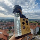
Step 6: Packaging, Final Assembly and Next Steps


Now that our soil moisture sensor is functional with battery power and deep sleep mode configured, the next crucial step is to properly package and assemble the entire setup to ensure durability and reliability, especially outdoors.
I selected a weatherproof enclosure in the form of an electrical junction box that can withstand garden conditions.
To mount the soil sensor, I made a grove in the electrical box bottom and I then epoxied the sensor in it. This way when we add the box in the garden, the sensor will be in the soil while the box will sit on top of it.
I glued the batteries with some hot glue to the electrical box and I connected everything up for the final test on my bench. Once I'm confident that everything works as expected, I'll move the sensor outside.
The full code of the device is available on my website article for the soil moisture sensor.
If you are interested in updates about the sensor and its operation, be sure to subscribe to my YouTube channel. You can also check out my other Instructables and projects for more interesting stuff.

This is an entry in the
For the Home Contest


