

Introduction: CNC & Manual Touch Probe.


A touch probe of the type described here was invented by Sir David McMurtry, co-founder of the Renishaw company, for inspecting parts of the Concorde engines. They are now used extensively on CNC milling machines, as well as CMMs (Coordinate Measuring Machines), unfortunately the offerings from companies like Renishaw are priced in the thousands of dollars range. The probes are used for machining setups and component inspection, also used for touch scanning of 3D surfaces for reverse engineering.
The principle and main components are really quite simple and the net is full of videos and photos of home built versions. Many DIY versions are fairly crude but others are of good quality, albeit not up to the insane accuracies (sub micron level) of top of the range probes, but well within the range of the needs of normal machining.
Many DIY probes are made by and for people to do 3D scanning for replicating profiles in wood with CNC routers where great accuracy is neither possible nor required. In my case I have two anticipated uses, firstly I often use my milling machine to reverse engineer objects such as motorcycle crankcases to determine bearing bore centres and diameters etc., in other words to use my mill as a poor man's CMM. Secondly, I plan to use it for part location and alignment on a milling machine. In the past I have used tradition edge finders and dial indicators for such tasks but I am anticipating that the probe will be quicker.
My milling machine has good quality DROs with glass scales, but the minimum resolution is 0.01 mm, I want the resolution and repeatability of my probe to at least be better than that.
Step 1: Theory of Operation


The basic principle of this type of probe is that the continuity of an electric circuit is broken when the probe touches a feature in the XY plane at a given Z position or touches a surface in the Z direction at a given X & Y.
Many CNC programmes are available to automatically do this scanning over a preset grid, but it can usually be done manually also. At the moment I anticipate using it manually, that is positioning the mill coordinates by hand.
It is usual to have six balls (I used 6.35 mm balls from a ball bearing) and three pins (I used 6 mm hardened dowel pins) to form an electrically conductive path. The balls are arranged in an insulating material (I used Delrin) in a circular pattern of three pairs and electrically connected in a series. The main photo above shows the principle diagrammatically. The pins are mounted in another piece of insulating material arranged 120 degrees apart to match the spacing of the balls. This piece has a stylus attached which is used to touch the object being measured. Photos in other steps show this better than my words can.
When the top piece with the pins is spring loaded onto the lower piece with the balls the electrical circuit is closed. Even small movements of the stylus will slightly lift at least one of the pins and break the connection thus signalling that the stylus has contacted the work piece. This needs the stylus to have been displaced by a small amount, called "pre-travel" which represents an error in the measurement, however as long as this pre-travel is repeatable it can be allowed for on each of the three axis in the measuring software or manual calculations. Resolution and repeatability are more important than pre-travel.
Ball spacing where the pins sit is an important consideration. The second photo show three possibilities. If the gap between the balls is the same as the pin diameter then location of the pin and hence the stylus will be very good but the pin will need to lift significantly to break the circuit, in other words the pre-travel will be excessive. The other extreme would be with zero gap between the ball centres, in this case the pins would sit on top of both balls together. This would give us the minimum pre-travel but there would be no pin location stability. It is obvious then, that we need to compromise between these two extremes. I have no idea what quality commercial probes use for the contact angle but I went half way and selected 45 degrees as my compromise between the best stylus location and the minimum pre-travel.
The electrical output is like a switch, basically on/off, many DIY probes are fed directly into the CNC controller such as Mach3, but for good repeatable results it is best to use a little bit of intermediate electronics such as a comparator to more accurately determine the switching point. There is an intermediate range between pure on/off in which the contact resistance varies between near zero and near infinite. Using a comparator enables detection of a small change in resistance which allows earlier detection of stylus touch, thus reducing pre-travel and improving repeatability.
A analog multimeter is the simplest way (but least convenient) to monitor the switching state using the resistance feature. In fact that is what I used for my first "does it work" test.
Step 2: Tools and Materials

As always, different makers will have different tools and materials available and so detail design points can be varied to suit anybody who might want to build their own. The following is a listing of the tools that I had available and materials out of my scrap box, there was nothing that I had to go and buy although I have ordered a Renishaw ruby tipped stylus. That might not be the case with everybody but none of the materials are expensive.
Tools
- Milling machine. It is unlikely that this project will be built by people without a milling machine or CNC router.
- Rotary table with chuck for a milling machine, or CNC capability.
- Lathe
- Drill bits and milling cutters.
- 3 mm thread tap
- Soldering iron
Materials
- Short length of 50 mm diameter 6 mm wall aluminium tube. I used 6061 but the grade is unimportant.
- Very short length of 38 mm diameter aluminium bar for the endcap.
- 6 x balls from ball bearing I used 6.35 mm (1/4") but 4 mm to 7 mm should do OK.
- 3 x 6 mm dowell pins. I would suggest these should be close to the ball diameter.
- Short length of 12 mm steel bar. This is for mounting the device to a chuck or collet. It could any size to fit available chuck or collets but I would suggest 12 mm or greater for rigidity.
- Short length of 50 mm diameter Delrin or other hard plastic.
- 3 x M3 screws.
- Thin copper wire.
- Solder flux.
- Solder.
- Two core connecting cable. I used audio speaker cable which is shielded.
- Stylus. As a temporary measure I made my own by soft soldering a ball onto an M6 bolt.
- Small spring.
- A few resistors, capacitors, LED and a comparator chip (LM293, LM393). if you want to avoid using the contacts directly.
Step 3: Base Section - Machining


The base section closes off the lower part of the probe assembly and provides the mounting for the 6 balls.
This involved some lathe turning and milling. The milling required accurate indexing for drilling holes for the balls, this could have been done by writing some simple G code to use CNC features but I thought it both quicker and better for the purposes of demonstration to use a rotary table with chuck. The lathe work could also be done on the mill with the rotary table if a lathe is not available.
Firstly a spigot was turned to fit inside the aluminium outer tube, then the ball holes were made using a flat ended 6.35 mm (1/4") milling cutter. The holes were accurately made to the same depth and the flat bottom was used to ensure a good vertical location of the balls. A separate test had shown that making a hole with the milling cutter gave a very slight interference fit on the balls which enabled their fitting without glue.
Radial grooves were milled for clearance for the pins and tangential grooves made for the connecting wires between the balls. An angled hole was drilled in a drill press for the external cable.
Step 4: Soldering the Balls


Firstly I ground small flats on the balls as a place to solder the wires to. This meant that at least most of the solder remained within the sphere of the ball preventing problems of fit into their mounting holes in the base. The first photo shows the flat on the ball in the foreground and a pair of connected balls.
I used very thin copper wire for the connections because it was easier to solder to the balls. The balls were supported in a brass rod with a hole to sit in. The bar was first warmed as a heat source to keep the balls warm to facilitate the soldering. A small drop of non-rosin based flux was put onto the flat section and a touch with a soldering iron quickly tinned the ball ready to take the pre-tinned copper wire.
Step 5: Stylus Holder


To start, I turned part of the Delrin bar down to 34 mm diameter, a loose fit into the 38 mm ID aluminium tube body, to allow free movement. I left part of the bar at its original 50 mm for secure holding in a chuck. Then I chucked it up on the rotary table and drilled 3 holes 120 degrees apart for the pins.
Back to the lathe to turn it down and face off to expose near half of the diameter of the pins. I did it this way because drilling full round holes is easier and more accurate than drilling half a hole. A tit was left on the large end as a location for the spring.
The pins were cut to length and fitted to the stylus holder piece.
Step 6: Main Body


This is the main structural piece which holds the whole thing together. The tube was parted off and faced in the lathe.
The endcap was drilled and reamed a tad undersize for the mounting shaft which extended inside as a guide for the spring. Then it was pressed into the tube. Neither the 38 mm bar nor the tube needed any addition machining to obtain a strong interference fit.
Step 7: Partial Assembly

The photo above shows clearly how the top and bottom Delrin pieces go together aligned kinematically by the balls and pins. There is only a single stylus location that geometry allows when the pins are in contact with each pair of balls. So whenever the stylus is displaced by a touch the spring forces the pins onto the balls ensuring repeatably accurate realignment of the stylus assembly.
Step 8: Stylus

I have ordered a Renishaw ruby tipped stylus but being impatient to try the probe I made a temporary one by soft soldering a hardened ball onto a reduced diameter M6 bolt. It works well and quite frankly, for the relatively small amount of use that I will give the probe, I wonder whether the professional stylus will do any better.
Step 9: All Together

Shown here is the completed assembly. Note the three M3 screws holding the Delrin piece to the main body. These were deliberately not drilled at 120 degree intervals to ensure that it had to always go together with the same orientation. A small indent was drilled in the main housing to indicate the cable position as a rapid guide to the correct hole alignment. Maybe a bit OCD but ........
The main body was drilled 2.5 mm and tapped for the M3 screws.
Step 10: Sensing the Touch and the Future.


I have mentioned in another step that it is better to add some electronics to get a more precise and repeatable touch sensing.
Initially I just used a resistance range on a multimeter to check that the probe actually functioned. Once that was done I put together a simple breadboard prototype of a comparator circuit to control an LED as the touch indicator. The first schematic shows the LED connections for the LED to be turned OFF when a touch is sensed and the other shows the simple change needed to light the LED on touch.
It is possible to simply put a LED and current limiting resistor in series with the probe contacts but I fear that the contact areas of the balls and pins would become pitted over time due to the current needed for the LED. On the other hand it is necessary to pass a current high enough to ensure continuity. Very small currents often lead to unreliable contact continuity. I opted to use 5 mA which I guessed as enough to get reliable contact without degrading the contact area.
I have for some time been thinking about using an Arduino to read the position of the slides on my mill to permit rapid startup when I use the mill in manual mode. Currently, I have to start a PC and CNC system just to read the slides. When I get around to that it will be a simple matter to input the probe state and record touch positions automatically. I'll make another instructable if and when that happens.
Step 11: Boxing the Electrons.


To house the simple electronics I used a 3D printer to make a simple box designed to bolt to the aluminium housing. It could have been made smaller but the extra space provides some future proofing.
The front side of the box has two LEDs, a green one for power on indication and red one as the touch indicator. On the rear of the box are two connections, one for 5 V power and the other to connect to a CNC controller (optional).
Step 12: Accuracy Tests

I take nothing at face value when it comes to measuring stuff, so before trusting the probe as a useful tool I measured resolution, repeatability and accuracy.
My milling machine has DROs on each axis with a resolution of 0.01 mm. I wish that it was less but it is what I have and is OK for most of my work. So my first concern was that the probe resolution and repeatability were no worse than the DROs. To test these parameters I clamped a 123 block to angle plate on the mill table. I could have used the angle plate directly but the surface finish was not as good as the ground finish on the 123 block. Then I moved the mill table until my LED indicator signalled a touch. I repeated this 20 times on each axis, in all cases the DROs showed the same readings indicating that the probe was at least as good as the measuring ability of the mill. It also confirmed that the pre-travel on any axis was very consistent.
The next series of tests concerned the accuracy of measuring bores and raised features. To do this I moved the mill table so that the probe approached the 123 block from opposite sides and noted the DRO readings. The difference in the values from each side of the block should equal the actual width of the block plus the stylus ball diameter, those two dimensions were 25.40 mm and 4.76 mm respectively, giving 30.16 mm as the value to check the probe against. The probe gave 100% consistent values of 30.13 mm when measuring along the X axis and 30.11 mm along the Y axis. This means that there is an error (pre-travel) of 0.015 mm on the X and 0.025 mm on the Y. However, as this was consistent over more than 20 tests it is possible to add twice the pre-travel to the measured difference to eliminate the error and obtain accurate results. When using CNC probing most controllers allow for the entry of such data.
Accurate results depend to some extent on the force needed to make the stylus move. If the spring is too stiff then structural deformation can add to the pre-travel and if it is too soft then the pins may not seat onto the balls correctly after each touch, leaving the contacts in the open state. Some commercial probes have adjustment features for the spring force. For simplicity I avoided adjustment in favour of trial and error/success. My initial spring needed around 8 N on the Z axis to signal a touch and around 1 to 1.5 N on the X and Y axes. The force required on the X and Y axes depends on whether the touch is on one side of the probe ball or the other, this is due to the geometric effects of the triangular layout of the contact points (balls and pins).
This first spring gave good results but it "felt" a little too strong, I then tried another spring with near half the assembled force. That also worked fine and reduced the pre-travel a little. I decided to use that spring and I did not try others.
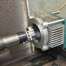
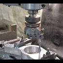
Step 13: Typical Usage

Here we can see an example of the typical usage that I made the probe for.
The photo shows inspecting a motorcycle crankcase that I machined from a solid block. The probe is a big time saver over the methods that I used in the past.


