

Introduction: Carbon Fiber Aircraft Flap


Carbon fiber composites have been used for decades in high-performance applications that require high strength and lightweight components. Making something out of carbon fiber may seem daunting at first, so the goal of this Instructable is to demonstrate composite manufacturing techniques and provide a list of materials and vendors.
This aircraft flap contains four pieces that are bonded together using adhesives and fasteners. The leading edge, lower, and upper panels contain honeycomb core. The spar in the middle does not contain a honeycomb core and only contains carbon fiber plies.
5 Milestones
- Mold preparation (Steps 1 - 38)
- Honeycomb core preparation and carbon fiber cutting (Steps 39 -42)
- Layup in molds (Steps 43 - 60)
- Cure (Steps 61 - 72)
- Machine and bond (Steps 73 - 98)
Mold Care Products
- Waterworks
- FreKote (Solvent based)
Edge Filler
- Huntsman Epocast 1629 A/B Edge Filler (Click the bottom link - 'US Aerospace Materials for Production and Assembly' for a great list of products).
Mold Core Films
Carbon Fiber
Vendors
Shop Equipment
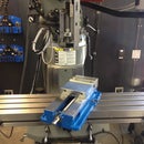
- Assembly Guidance - Laser Layup Projection System
- Gerber Technology - Ply Cutting
- Cleco-Style Clamps
- UE Leak Detectors
Vacuum Bagging
- Polyester Peel Ply
- Low Lint Rymplecloth (good stuff and $20. You can easily spend $100!)
- Flash Tape
- Sealant Tape
- Thru-Bag Vacuum Connector
- Breather and Bleeder
- Polyethylene Vacuum Bag
- Air Hose
- Vacuum Pump
- Vacuum Gauge
- Perforated Release Film
- Breather
- High Temperature Solid Release
- Vacuum Bagging Techniques
Machining Composites
Surface Preparation
Fasteners
Books
Websites
Resin Infusion
- DelStar Technology - Surface Flow Media
Learn Composites
- Abaris Training (this Instructable covers Manufacturing 2 & 3 courses)
- Cerritos College
- Metropolitan State University of Denver
Step 1: Prepare Molds

Pictured are the molds (tooling) that will make our parts. They are made out of fiberglass. Making the molds is a topic in itself, so look at the details of each mold and ask yourself why.
Molds must have a smooth surface that doesn't stick (chemically bond) to our final carbon fiber part. To achieve this clean the mold, seal it, and apply mold release.
Step 2: Clean Molds - Remove Old Resin


Clean molds every 2 - 10 parts or until there's an excessive build-up of mold release.
Remove leftover resin using huge popsicle sticks (tongue depressors) that have their ends sanded to create a wedge tip. Use proper tools and a lot of care to avoid damaging the mold. The soft tip tongue depressor will remove resin, but won't damage the mold.
Step 3: You Want to Remove Gunk (Resin) Like This

Use the modified tongue depressor to remove leftover resin.
Step 4: Clean Molds - Razor Blades


If you must use a razor blade, be very careful! The mold is very important and proper care is essential.
Here's how you use a razor blade to remove resin:
1. Dull the blade by dragging it across the table. This slightly bends the sharp edge of the blade and prevents inadvertently gouging the part.
2. Remove resin very carefully! Don't be surprised if a manger stops you from doing this - molds are expensive.
Step 5: Clean Molds - Be Careful

Some people like using a Painter's knife to remove resin from a mold. If you choose this unweildy tool, OMG be careful. Gouging the mold is not an option.
Step 6: Seal Molds


Seal the mold using Waterworks PreFlight Tool Surface Conditioner (or solvent-based FreKote B-15 or 700-NC). This fills microscopic imperfections in the mold and makes a smooth surface.
There are many steps to properly apply Waterworks PreFlight Tool Surface Conditioner.

Step 7: Seal Molds - Apply a Thin Coat


Apply a thin coat of PreFlight with lint-free cloth.
Wipe in one direction.
Wait 15 minutes.
Stay awesome.
Step 8: Seal Molds - Apply a Second Thin Coat

Apply a second thin coat.
After you apply this thin coat, use a fresh lint-free cloth to immediately wipe it off.
Wait 15 minutes.
Step 9: Seal Molds - Apply a Third Thin Coat

Apply a third thin coat.
Just like the previous step, immediately wipe it off.
Wait 15 minutes.
Step 10: Seal Molds - Done. Sealed.

The book says we should seal and wipe off a fourth time and cure for 15 minutes at 180 degrees Fahrenheit. We are skipping that.
Experience says: "We are done. The mold is sealed." Word.
Step 11: Tape Mold Border


Apply flash tape to the perimeter of the mold. Flash tape doesn't leave a residue and can withstand high temperatures.
Step 12: Mold Release


The mold is cleaned, sealed and ready for mold release. Apply Waterworks Departure (solvent-based FreKote B-15 or 700-NC is also a great option).
Step 13: Apply Mold Release


Lightly spray molds.
Wait 60 seconds and wipe with lint-free cloth.
Wait 15 minutes for mold release to cure.
Step 14: Mold Core Prep - Stabilization With Edge Filler


The leading edge and lower flap surface are sandwich panels that contain core material. Sandwich panels act similar to an I-beam - the core is a middle-web separating the two carbon fiber laminates. This significantly increases the strength of the composite while slightly increasing weight. There are a variety of core materials with various advantages and disadvantages - please read Chapter 6 Core Materials in Essentials of Advanced Composite Fabrication & Repair.
The core (we are using honeycomb) needs to be cut to size and chamfered on each edge (see finished stack above).
Honeycomb core is flexible and difficult to machine (we need to cut chamfers or angles on each edge), so we need to do something to make it more rigid and machinable. We used two methods to make the honeycomb more rigid:
- Stabilization (aka potting) using Epocast 1629 A/B Edge Filler
- Film adhesive - Hysol EA 9696 Film Adhesive
Step 15: Mold Core Prep - Measure Honeycomb


- Use engineering drawings or a template to mark the outer edge of the chamfer of the honeycomb core.
- Apply flash tape approximately 0.5" inside the line.
Step 16: Mold Core Prep - Stabilization (Potting) - the Goods


Epocast 1629 A/B edge filler is like playdough for adults - it's extremely lightweight and kinda fun to play with. Epocast 1629 is manufactured by Huntsman and is an ultra-low density, two-component edge and void filler. We use this to stabilize (aka potting) the honeycomb core. Stabilizing makes the honeycomb core more rigid so we can machine the edges.
Mix a batch and start applying edge filler to the perimeter using a putty knife.
Place white polyester peel ply on the surface of the table. This ensures air escapes honeycomb cells when edge filler is applied.
Attachments
Step 17: Mold Core Prep - Edge Filling


Ensure the edge filler penetrates the entire honeycomb.
Flip honeycomb and check the bottom to verify proper application.
Step 18: Mold Core Prep - Edge Filling Complete


Edge filler has been sufficiently applied to this core. It should take about 10 minutes to do this.
Step 19: Mold Core Prep - Vacuum Bag 1

Vacuum bags provide compaction pressure by removing air from inside the bag and allowing air above it (atmospheric pressure) to push down on the bag and its contents. This compaction pressure helps shape the part. In this case, the upper and lower panels of the flap are flat. The vacuum bag provides even compaction pressure while the honeycomb + edge filler combo cure in the oven.
- Obtain a flat tool (caul plate). This will be the flat base for our vacuum bag.
- Apply blue flash tape to the entire perimeter (it's hard to see in the picture. The flash tape looks black because it's around the perimeter of the caul plate and the caul plate is black).
Step 20: Mold Core Prep - Vacuum Bag 2

- Apply blue high temperature solid release film to caul plate and tape the perimeter with blue flash tape. Since the caul plate is black, covering it with a blue sheet makes it look green! fyi
- Apply sealant tape on top of the flash tape perimeter. Sealant tape is like a huge roll of silly putty and it's very tacky. Leave the top backing on while we make the rest of the vacuum bag.
Step 21: Mold Core Prep - Vacuum Bag 3

- Cut individual sheets of polyester peel ply and lay flat (picture shows this is already done. It is already underneath the honeycomb core).
- Place edge filled honeycomb on top of this (picture above).
Step 22: Mold Core Prep - Vacuum Bag 4

- Place another layer of white polyester peel ply on top of edge filled honeycomb.
- Cut four corners of top polyester peel ply to ensure it lays flat when vacuum is applied.
Step 23: Mold Core Prep - Vacuum Bag 5

The vacuum port will work best if placed in the center of the tool.
- Place thru-bag vacuum connector on top of a piece of breather in the center of the tool. Breather ensures the thru-bag vacuum connector can draw air out of the vacuum bag.
Step 24: Mold Core Prep - Vacuum Bag 6

Expose the sealant tape in each corner. This allows us to properly position the vacuum bag.
Step 25: Mold Core Prep - Vacuum Bag 7

- Tack polyethylene vacuum bag to the sealant tape in each corner. Sealant tape comes in many colors.
- Remove backing on the remaining sealant tape and securely adhere vacuum bag to sealant tape.
Bonding vacuum bag and sealant tape
This is extremely important. Slight imperfections in the sealant tape to polyethylene vacuum bag interface can cause leaks which may result in inadequate vacuum. Work the vacuum bag and sealant tape with your hands to ensure an air-tight fit. Use a lot of pressure to ensure everything sticks together. You will be doing this a lot and will get plenty of practice! Take your time. If the seal is insufficient don't be afraid to start over - this is all part of your learning experience. Manufacturing composites takes a lot of patience and persistence. Never give up.
Vacuum bag
Integrity of the vacuum bag is very important. Ensure your work area is free of sharp objects to prevent inadvertently puncturing your vacuum bag.
Step 26: Mold Core Prep - Vacuum Bag 8

Use a new razor blade to cut a small slit in the vacuum bag directly above the female part of the thru-bag connector.
Step 27: Mold Core Prep - Vacuum Bag 9

Insert thru-bag connector coupling and rotate 1/4 turn clockwise. Don't rotate it fully clockwise as this will twist and pinch the vacuum bag and cause a leak.
Step 28: Mold Core Prep - Vacuum Bag 10

Connect air hose.
Step 29: Mold Core Prep - Vacuum Bag 11

Turn on vacuum pump. Set pump to 10 inches of vacuum to prevent crushing honeycomb core. As the vacuum is drawn you can now fully rotate the thru-bag connector clockwise. This ensures the bag is flat and there's a good seal at the connection.
Step 30: Mold Core Prep - Vacuum Bag 12

Check vacuum gauge. Ensure 10 inches of vacuum.
Step 31: Mold Core Prep - Vacuum Bag 13


Place vacuum bag in the oven.
Cure time
- Take a look at Epocast 1629 A/B edge filler data sheet
- We put it in the oven at 125 degrees Fahrenheit for 4 hours. Whatever. It worked.
Attachments
Step 32: Mold Core Prep - Vacuum Bag = DONE


Remove from oven. Remove bag. Remove blue flash tape. Now check out the awesome cured honeycomb edge filler. It is flat and still very lightweight (we used ultra-lightweight edge filler). This honeycomb core is considered 'stabilized' or 'potted.' The edges are rigid and now it can be machined.
Before that, let's stabilize the leading edge core using another method.
Step 33: Mold Core Prep - Stabilization With Film Adhesive


Stabilization with film adhesive ensures your honeycomb panel is flexible. Unlike the upper and lower panels, we want the leading edge honeycomb core to be flexible. The previous method, stabilization with edge filler, produced a rigid honeycomb core. We need a flexible honeycomb core for the concave leading edge.
Hysol EA 9696 Epoxy film adhesive is a thin film that will be bonded to one side of the leading edge honeycomb core. This will stabilize the honeycomb core so we can machine it.
Attachments
Step 34: Mold Core Prep - Apply Film Adhesive


- Use engineering drawings to measure and cut leading edge honeycomb core.
- Cut film adhesive approximately .25" oversized.
- Remove backing and apply to one side of honeycomb.
Step 35: Mold Core Prep - Film Adhesive Vacuum Bag


Similar to the honeycomb core with edge filler, we need a vacuum bag for the honeycomb core with film adhesive. Film adhesive contains resin. Time, temperature, and compaction (vacuum bag) results in a flat honeycomb core with film adhesive on one side. Film adhesive is flexible, so the core will be able to take the shape of the leading edge.
Blue flash tape in the center of honeycomb is an error. There's no need to apply flash tape there.
Vacuum bag
Similar to the cores with edge filler, we need a vacuum bag so things don't stick together, resin flows (more on that below) and there's compaction pressure. Steps covered in the picture above:
- Layer of solid release above caul plate
- Flash tape around perimeter
- Adhesive tape on top of flash tape
- Layer of white polyester peel ply
- Red perforated release film
- Honeycomb with film adhesive (adhesive side down)
I know that was a lot, so let's talk. The goal of the vacuum bag is the three things above - don't stick together, allow resin to flow, & pressure to compact everything.
Don't Stick Together
It wouldn't be any fun if plastic film was permanently bonded to our final part. We prevent this via the peel ply layer - it doesn't stick (made out of polyester or Teflon) and it absorbs some of the resin. Polyester (white stuff) peels off nicely and leaves a fairly rough (matte) surface. This is good for painting. Teflon (goldish) also peels off nicely, but leaves a much smoother surface that isn't as good for painting.
Allow Resin to Flow
As the resin heats up it turns into a less viscous liquid. We want to control rate at which it flows. This is why we slowly heat something up in the oven. This is called ramp rate and will depend on your resin (or film adhesive in this case). As the resin on the film adhesive becomes less viscous it flows and attaches to whatever is closest to it, or in this case, slightly up the wall of the honeycomb. As resin cures it off gases stuff called 'volatiles.' For vacuum bags cured in a oven, volatiles must be removed or they will displace resin and create voids. The combination of an oven and vacuum (which provides pressure on our part of 1 atmosphere) is not enough pressure to dissolve volatiles in the resin (although an autoclave does!), so they need a path to be evacuated. This the primary function of the vacuum pump. The red perforated film has holes in it and allows air and resin to flow through it before resin is absorbed in the white polyester peel ply. We are using perforated film because polyester peel ply would absorb too much resin.
Compaction
Removing air in the vacuum bag allows the air above it (atmospheric pressure exerts a pressure of 14.7 psi at sea level) to push on the bag and its contents. This shapes the part. Rigid aluminum molds or autoclaves also do this but have various advantages and disadvantages (expensive).
Step 36: Mold Core Prep - White Peel Ply


Add a layer of white polyester peel ply. This ensures nothing sticks together.
Step 37: Mold Core Prep - Final Bag & Cure


Seal the bag and draw vacuum. The same principles apply - ensure bag is air tight, place a thru-port connector, & draw vacuum.
Cure for 90 minutes at 250 degrees Fahrenheit. See data sheet above.
Attachments
Step 38: Mold Core Prep - Done


Remove from oven and remove vacuum bag.
Step 39: Machine Honeycomb


Both honeycomb cores are stabilized and are ready to be machined. Consult engineering drawings and mark outer perimeter of honeycomb. Use a band saw to cut to size.
Step 40: Machine Honeycomb Edges (Chamfers)


Set band saw to the proper angle and machine chamfers.
Step 41: Honeycomb Cores = DONE

Stack of finished cores with edge filler.
Step 42: Cut Carbon Fiber Plies


The aircraft flap uses 3K 70 plain weave carbon fiber with Hexcel F155 resin system. Use engineering drawings and/or templates to cut needed material. We are using prepreg carbon fiber - it comes prepared (impregnated) with the proper amount of resin. Prepreg contains resin that is ready to cure, so it must be kept in a freezer (-10 F) to slow down the chemical cross-linking reaction. It has a limited shelf life and time above freezing must be carefully logged.
Cutting Carbon Fiber
Use a sharp utility knife.
Step 43: Leading Edge Layup


Place the first ply in the prepared leading edge mold. It is very important to work the carbon into place with your fingers or a plastic scraper. I know this sounds simple, but this can be a very difficult step that the hasty maker will skip or not do properly. Take your time and ensure the carbon follows the exact contour of the mold. Look at the finished example part and carefully examine all curvatures and plan accordingly.
First, place the carbon at the lowest point in the mold and work it upwards. This should take you 10 minutes. Again, take your time. We are making a very high performance part and detailed work is essential.
Step 44: Leading Edge Layup - Debulking & Don't Stick Together


With the first ply in place, we need to perform something called 'debulking.' Debulking compacts the ply against the mold with a vacuum bag. We need to do this for each ply placed in the mold. Your effort will be rewarded.
So, let's make another vacuum bag! Pictured above is the first step. Vacuum bagging always comes back to the basics - don't stick together, air flow, & compaction.
Don't Stick Together
We applied mold release to the mold, so the ply won't stick to the mold. Done. Next, put red perforated release film on top of the first carbon ply. This has holes in it and allows the air to flow to the vacuum pump. Notice, I have two pieces of red perforated release with a 0.5" overlap in the center. This allows the perforated release film to move as pressure is applied.
Secure edges of perforated release film with flash tape.
Step 45: Leading Edge Layup - Air Flow


Air Flow
Place two pieces of white polyester peel ply on top of red perforated release film. This layer will function as a 'breather.' This provides additional space for air to flow. Tape edges with flash tape.
Step 46: Leading Edge Layup - Flash Tape Perimeter

Place flash tape around the perimeter of the mold.
Step 47: Leading Edge Layup - Sealant Tape


Apply sealant tape on top of the flash tape around the perimeter of the mold. This should be one continuous piece of sealant tape. When you approach a direction change, tear adhesive backing and continue in the new direction.
Step 48: Leading Edge Layup - Vacuum Bag Debulking

Compaction
The vacuum bag we are using does not stretch, therefore, we need to add expansion joints or 'pleats' in areas of high vacuum bag tension. Pleats are folds of extra vacuum bag that are typically 3" tall (easier to make if pleats are 3"). Areas of high vacuum bag tension occur in the curvatures of the mold. In this mold the lower left and right curves need pleats. See note in picture.
Connect to vacuum pump and debulk at 20 inches of vacuum for 15 minutes. This compacts the ply to the mold.
Step 49: Leading Edge Layup - Remove Vacuum Bag


It is necessary to debulk three more times, so we'll reuse this vacuum bag. Remove bag on one side and leave it attached on the opposite side.
Carefully raise breather and peel ply layers and check out your compacted first layer! Boom. This is a fairly extreme geometry for the carbon to conform to, so we're starting at the pro level right off the bat. Sweetness. You can do it.
Step 50: Leading Edge Layup - Ply 2


Repeat steps for the first ply and layup and debulk ply 2.
Step 51: Leading Edge Layup - Doubler


The next layer of carbon is called a 'doubler.' A doubler provides additional support to the edges of the leading edge while also bonding to the honeycomb core. We need additional thickness (plies) at the edge because this leading edge is joined using fasteners.
Pictured are the doublers. Layup doublers and debulk. Whoo hooo
Step 52: Leading Edge Layup - Honeycomb Core


Prepare the honeycomb core with film adhesive by lightly abrading film adhesive with red Scotch Bright.
Place honeycomb core with film adhesive in center of mold and place another layer of film adhesive on top. Take your time to carefully work the film adhesive around the honeycomb core.
Debulk, dude.
Step 53: Leading Edge Layup - Honeycomb Core Debulked

This is what the honeycomb core with film adhesive looks like debulked.
Step 54: Leading Edge Layup - Doublers


Add doublers around perimeter of honeycomb core with film adhesive. Doublers don't extend to the very top of the mold because this will be trimmed from the final part.
Step 55: Leading Edge Layup - Last Two Layers!


Add the last two layers of carbon one layer at a time. It should take you 10 minutes to work each layer into place. Take your time. Don't rush.
No need to debulk, since we will be making our final vacuum bag!
Step 56: Leading Edge Layup - Final Bag


Cut 5 pieces of white polyester peel ply and place them like this. Overlap edges by .25".
Step 57: Leading Edge Layup - Final Bag

Remove old vacuum bag and apply new sealant tape to perimeter.
Step 58: Leading Edge Layup - Final Bag Perforated Release Film

Place a layer perforated release film.
I should have cut this perforated release film into two pieces to allow for expansion. My bad.
Step 59: Leading Edge Layup - Final Bag Breather

Add a layer of breather. This allows air and volatiles to escape the composite while providing compaction pressure.
Step 60: Leading Edge Layup - Final Bag = DONE


Ensure the final vacuum bag doesn't have any holes coming off the stock roll and make the final vacuum bag. Add a thermocouple. Place pleats in areas of high curvature. Ensure there are no leaks by using flow meters, gauges, and audible leak detectors.
Step 61: Leading Edge Cure

Cure part at 250 degrees Fahrenheit for 90 minutes. Ramp up rate should be 2 - 8 degrees F per minute. Ramp down rate should be 2 - 8 degrees F per minute until 150 degrees F.
Step 62: Leading Edge Demolded


This baby looks good! Working the carbon in place one layer at a time and debulking paid off....big time. If we didn't do all that work the carbon layers will separate as pressure is applied. This results in 'bridging' (i.e. the laminates were not properly seated against the mold). Bridging creates pools of resin because the laminates were pulled off the mold and can ultimately result in a defective part.
Step 63: Leading Edge Stress Test


The leading edge weighs less than 1lb and can hold at least 200 lbs. This is why carbon fiber composites are so awesome and why we went though all the trouble! So sweet. So awesome.
Step 64: Spar


Making the spar is very similar to the leading edge - place each layer of carbon fiber into the mold, ensure it conforms to the contour of the mold, and debulk each layer.
Working the carbon into the corners is extremely important. Take the time to learn how the fabric stretches and work it into place.
Step 65: Spar - Autoclave Vacuum Bag

Once all layers have been debulked, it's time to make the final vacuum bag. The spar will be cured in an autoclave, so there'll be a few differences in the vacuum bag.
Step 66: Spar - Autoclave Peel Ply and High Temperature Solid Release


Place a layer of white polyester peel ply. I should have had two pieces, instead of one, that slightly overlap in the center. The white strings are fiberglass strands. These strings will help evacuate air or volatiles (if any) from the composite laminate. Its called string breathing.
Next, apply a layer of blue high temperature solid release. Tape the solid release around the perimeter of peel ply with flash tape. This ensures the entire laminate is completely sealed. This autoclave cycle will pressurize the laminate to 60 psi with nitrogen to a temperature of 260 F. Parts made in an autoclave have low porosity (air and volatile voids are minimized since the pressure either forces them out or dissolves them in solution) which results in better compression performance.
The white fiberglass strands extend beyond this solid layer and allows small amounts of air and resin (if any) to leave the laminate.
Step 67: Spar - Autoclave Breather

The primary reason for breather is to provide a path for air and volitales (when resin cures it emits a gas). Depending on your resin system and environmental conditions you may or may not generate volatiles. We used one layer of 10 once breather for an autoclave at 60 psi. At this pressure the breather will compress to the thickness of a paper towel....thin, but not thin enough to breath and still remove volatiles.
Step 68: Spar - Autoclave Sealant Tape

Remove flash tape around perimeter of mold and apply sealant tape.
Step 69: Spar - Autoclave Vacuum Bag


Make a vacuum bag, insert two thru-bag connectors, and draw vacuum. This bag has two ports because one port draws vacuum and the other port is used for monitoring pressure. Check for leaks using a gauge. The bag cannot have leaks and must hold vacuum.
Step 70: Spar - Autoclave Cure


Cure at 260 degrees Fahrenheit for 90 minutes with ramp rate of 5 degrees per minute.
Step 71: Spar - Demold


Remove vacuum bag and check out your part!
Step 72: Upper and Lower Panels - Demold


We'll let these two part magically appear. They contain the edge stabilized honeycomb core and are easy to make compared to the leading edge and spar.
Step 73: Machining Composites


Compistes cut well with band saws and are easily sanded, but using a router will require special bits. McMasterCarr has a good selection of carbide router bits.
Use a trim template to trim each composite part. I would rather use a CNC machine or robot arm to do this.
Step 74: Assemble the Parts - Fixtures


Tooling is extremely important when manufacturing composites. Investing in good tooling will ensure consistent parts and higher output.
Test fit your part in the fixture. We are using an adhesive to join the upper panel, lower panel and spar together.
Step 75: Assemble the Parts - Wax the Fixture


Apply an even coat of wax and immediate buff. Wait 10 minutes before applying a second coat. Apply three coats.
Step 76: Prepare Parts for Adhesive


The leading edge does not require adhesives since we will use fasteners. Place flash tap in areas of potential adhesive runoff. This will help us remove excess adhesive after curing.
Step 77: Surface Preparation for Adhesive
Hysol has a great Surface Preparation Guide.
Read page 176 - 179 in Essentials of Advanced Composite Repair
Attachments
Step 78: Composite Surface Prep - Before


This is what the surface looks like before preparing the surface. Notice the texture.
Step 79: Composite Surface Prep - After


There are three options for preparing the composite surface for adhesive - 180 grit sand paper, red Scotch Bright, or sand blasting.
Ensure you abrade resin and not carbon fiber. If you get black dust, you are removing carbon fiber.
The pictures show the surface is prepped. It is shiny.
Step 80: Composite Surface Prep - Wipe Clean


Wipe the prepared surface with a lint-free cloth. Use a fresh side of the cloth for each wipe. The surface is clean when the cloth is clean.
Step 81: Composite Surface Prep - Water Break Test


Test the energy of the abraded surface by applying water and holding the part at 30 degrees. The water should evenly coat the prepared surface. Don't do this on your actual part, do this on a sample part.
If you perform this test, re-energize the surface by lightly abrading the surface with sand paper and wipe clean.
Read page 179 in Essentials of Advanced Composite Repair and Design
Step 82: Bonding Parts - Apply Adhesive


We used Hysol EA 9309.3NA adhesive. This stuff worked great. See the data sheet above for the specs. Wear clothes you don't care about when playing with this stuff.
Read page 186 in Essentials of Advanced Composite Repair and Design
Attachments
Step 83: Bonding the Parts


Bond the parts. Cleco-style clamps hold things together nicely.
Step 84: Remove Flash Tape

And admire your part.
Step 85: Drill Leading Edge


Use high speeds and low feeds when machining composites. Use brad-point carbide drills for carbon fiber composites.
Use a template to locate the holes in the leading edge
Step 86: Insert Hole Grip Clamp


Drill one hole and insert a hole grip clamp.
Step 87: Insert 2nd Hole Insert Grip Clamp

Drill another hole on the opposite side and insert an additional hole grip clamp. This ensures the templates stays in place while drilling the remaining holes.
Step 88: Drill Remaining Holes

Drill baby, drill. Try not to drop the drill and break the only brad-point drill available. You will loose cool point....totes for real.
Step 89: Match Drill Holes


Align leading edge with trailing edge and clamp together. Use holes in leading edge to match drill holes in the trailing edge. Use hole grip clamps to keep everything peachy.
Step 90: Countersink Leading Edge Holes

Carbon fiber composites use 130 degree countersinks. Composites are thin, so we need the extra draft.
Step 91: Fasteners

There are a variety of fasteners and systems for joining composites. We used Click Bond fasteners. Alcoa Huck fasteners are also popular. See data sheet above.
Attachments
Step 92: Adhesive Mixing Tubes


This is a mixing tube attached to a two-part adhesive. Mixing tubes are great. They are easy to use and ensure repeatability. Controlling the manufacturing process is critical.
Push CB200 adhesive through the mixing tube and discard two inches of mixing tube length. This ensures the adhesive is thoroughly mixed.
If you don't use all the adhesive, do not remove the mixing tube! Place the entire assembly in the freezer. When needed again, remove old mixing tube and install a new one.
Step 93: Prepare Surface

Prepare the surface of composite by abrading the resin with red Scotch Bright. This prepares the surface for adhesive.
Read page 176 - 179 in Essentials of Advanced Composite Repair
Step 94: Apply Adhesive and Insert Nutpate


We'll be using something called a nutplate. Specifically, this is a #8 floating nutplate. Apply CB200 adhesive and insert. Repeat for all holes.
Step 95: Adhesive Cured

Adhesive turns green when cured.
Step 96: Remove Tabs


Pull orange tabs
Step 97: Insert Screws


Do not over-torque!
Step 98: Finished Carbon Fiber Aircraft Flap


Weigh the part. It weighs 1233 grams or just under 3 lbs. Amazing. Seriously amazing. This is engineering and human ingenuity at its best. This flap will withstand thousands of pounds of force before failing and it only weighs a couple pounds. Let's go to mars....or make an amazing airplane. I'm in.
Thanks for reading. I certainly enjoyed the journey and sharing my experience with you. Make cool stuff.


