

Introduction: Cetus 3D Printer Enclosure (Free Plans and .stl Files)

In May 2017 I bought a Cetus 3D printer, I'd wanted a 3D printer for a while but didn't want something that I'd spend more time fixing than using. The Cetus seemed to bridge the gap between reasonable value and sensible quality. Over the past year I've printed several useful items (and many useless ones). I've played with a few materials and found which work best for me and the printer (PLA for quick prototyping and PETG for more durable parts). Although I was very happy with the printer I've found a few things I wanted to improve:
- The extruder head drops when the printer loses power, everyone with a Cetus mkI knows this and in June 2017 an official fix was released which solves it. https://wwww.cetus3d.com/index.php?r=moshop/info&i...
- Like everything in my house the printer quickly gets covered in dust, which doesn't really affect the function of the printer but doesn't look very nice and it's a fiddle to clean all the small parts.
- The printer is loud, not ridiculously loud but enough to be annoying when I'm trying to watch YouTube on my laptop next to it.
I decided the best solution was store the printer in a zero-gravity vacuum chamber, but as I couldn't afford that I instead decided to build a simple enclosure. I researched a few different designs online but couldn't find anything that was quite what I wanted so designed my own. I made engineering drawings to help with making each part and for easy assembly, .stl files for all the 3D printed parts and schematics for the electronic parts. All of these are free to use and can be found at the end of this Instructable.
Step 1: Requirements


After searching photos online I sketched a few ideas but before I jumped into the detailed design I came up with a list of what I wanted from my new enclosure:
Must:
- Provide a low dust environment - On my desk without any enclosure the printer quickly gets dusty and is fiddly to clean.
- Be easy to open to access the printer - It mustn't be awkward to remove parts, change filament, change extruder etc.
- Be compact - I have an old office filing cabinet in my room which would be ideal for storing the printer on.
Would be nice:
- Noise reduction - The fan noise is quite annoying during a long print, and on the Cetus 3D printer the fan is always running when the printer is powered on, even when it's not printing. Also all the beeps are very loud, although I printed one of these www.thingiverse.com/thing:31957 which helps with that.
- Temperature regulation - Although I haven't noticed a need for this for anything I've printed yet, it can't hurt and might be useful if I attempt printing with other materials.
- Storage for 3D printing tools and paraphernalia - This would save me constantly having to find the cardboard box where I currently keep the scraper, spare nozzles, etc.
- Look good - What's the point in making something that doesn't look good!
- Not be expensive - I didn't exactly set a budget for the project, and I had some of the materials already, but if it costs many hundreds of pounds I may as well just buy a more expensive printer which is already enclosed.
Step 2: Mechanical Design


The first thing I did was I measured the printer and filament holder, I used the axis calibration tools in the Cetus software to move the x, y & z axes fully to get a maximum size envelope, then modelled it in CAD to use as a 'dummy' component. Even though it made the overall dimensions bigger and may make filament changes slightly more fiddly I decided to have the filament inside to keep it dust-free as well, many 3D printer enclosures only enclose the printer and not the filament. I decided to design the enclosure so that it can be easily lifted off the printer for maintenance if needed, so the panels of the enclosure must be rigid enough without a base panel.
I wanted to make something a bit more interesting than just a simple box with a door on the front so I searched online for ideas. I came across this http://moczys.com/2015/01/03/3d-printer-enclosure...series of posts and liked the overall shape of the enclosure with the angled front. I thought it would be useful for the acrylic door to open upwards and out of the way, and I remembered something I'd seen several years ago on www.woodgears.ca (one of my favourite websites, please take a look, especially if you're interested in woodworking) This clever mechanism http://woodgears.ca/tool_holders/toolchest.html allows the front half of the box to flip up and over to sit on top of the back half of the box. I tried drawing this out but couldn't get the geometry to work for the size of box I wanted and I didn't know how I'd make the thin wire hinge pieces rigid enough. I ended up designing a hinged lid that works in a similar way using bolts and threaded bars and will lift up and balance on the back half of the enclosure. I had to make one of the hinge arms curved to clear the other parts and added two thinner pieces on the outside of the main hinge for support. I think this resulted in an interesting looking door mechanism which is hopefully practical.
I designed the parts in Solidworks as that's what I use in my work as a mechanical engineer and I've managed to hold on to a student license from my university. Solidworks is an excellent tool for designing complex parts and large assemblies with moving parts, but it takes practice and skill to use it efficiently. I've had quite a bit of experience modelling assemblies with hundred of complex components in Solidworks but I'm still learning new things about it.
I had a piece of 10mm MDF left over from another project so I sized the main frame pieces to fit within that sheet. I chose 3mm acrylic for the hinged door to keep it fairly lightweight. Although I ended up using 6mm acrylic for the top panel of the door in order to move the centre-of-mass higher to make sure it would stay balanced on top of the box. I ended up with an overall enclosure size of 520(d)x400(w)x435(h), not including any external fasteners and control knobs. I added a pair of PC fans into the top panel with activated carbon foam filters to hopefully keep any circulating air dust-free.
To add strength and rigidity to the acrylic door near the hinges I designed some L shaped supports which can be glued to the acrylic panels. I designed these supports, the hinges and the door handle to be 3d-printed. I also designed some 3D-printed potentiometer knobs purely because I can (more on what those knobs control in the next section).
To help the hinges to move smoothly I designed some small bushes to be machined from aluminium bar. These aren't absolutely neccessary, I'm sure the mechanism would work well enough with the plastic parts rotating directly on the threaded bar but these are fairly simple parts to machine and I think they are worth the extra effort to make. Note, if you build this enclosure without these bushings you will have to change the diameter of the holes in the 3D-printed hinge parts.
I then created some engineering drawings from the Solidworks components to use while making each part. Normally I wouldn't go to this much effort for a home project. However I've got plenty of experience making them so they don't take me long, most of the work was already done by modelling the parts in CAD anyway and it saves a lot of mistakes when working with complex shapes. All of the drawings and .stl files you need to build the enclosure as well as a 3D .pdf and .step file of the whole assembly for reference are available to download at the end of this Instructable.
Step 3: Electronics Design


I don't have much experience with electronics but I feel like I know the basics and have recently starting playing with Arduinos. I knew I wanted to control a pair of PC fans for air circulation and I thought some colour changing led strip would look good. The obvious route for controlling these was an Arduino so I made a prototype circuit on a breadboard and wrote some simple code to let me control the speed of the fans and the led brightness with a couple of potentiometers. The LEDs cycle between red, green and blue at a set frequency. My code is not very well written but it does the job.
For power I used a 12v transformer and a female DC jack connector with screw terminals which can be installed in the back panel of the enclosure. I also added a separate power switch which will fit next to the potentiometers. The Arduino takes inputs from the two potentiometers and converts them to PWM output signals which power the LEDs and PC fans through N-Channel MOSFETs.
I wanted the electronics to fit into a top corner of the enclosure and not get in the way during filament changing so I used Fritzing to layout the circuit onto a fairly compact piece of perfboard which can be screwed to the inside of the back panel. The wires for the LED strip and fans are connected to the board with screw terminals rather than soldered directly to make it easier to assemble. The Fritzing file and Arduino code are available to download at the end of this Instructable.
Step 4: Electronics Assembly
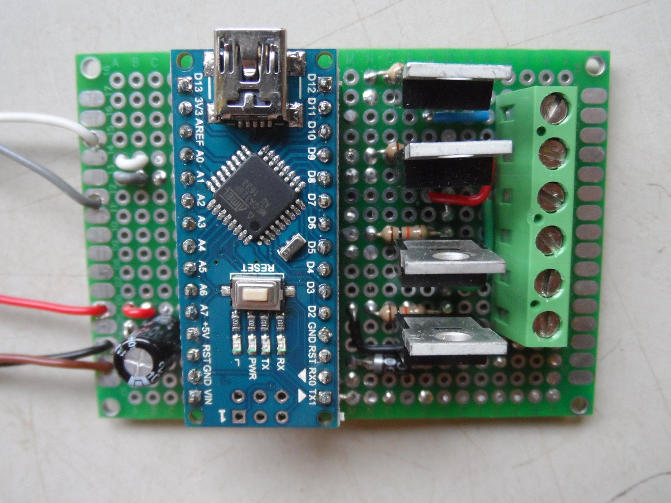


Using my electronics drawings I assembled all the electronic components onto a piece of double sided prototype board and soldered lengths of uninsulated hook up wire to bridge between components. When soldering trailing wires onto a board I like to loop the wire through a predrilled hole before soldering to give it some strain relief. When the board was soldered I connected the 12v power supply, switch, potentiometers, LED strip and a fan and checked that the board worked as intended.
Step 5: Making MDF Parts


Using my engineering drawings I drew the outlines of the parts onto a sheet of MDF then scored the lines with a knife to leave an accurate mark. The parts were too big to cut out with my table saw and bandsaw so I had to use my circular saw and jigsaw then sanded the edges down to the score-lines. After measuring and marking the hole positions from my drawings I drilled the holes in the parts. I cut the rebates (or rabbets for the Americans) and the internal grooves with my router and a straight edge guide. If you have access to one a CNC machine would speed up cutting of these parts. After making all the MDF parts I test-fitted them together before gluing. I made sure to clamp the parts squarely while gluing otherwise the acrylic section wouldn't fit neatly later.
After gluing the MDF parts together I hand planed the front edge of the top panel to match the angle of the side panels. I sanded the joints and applied fine filler to any small gaps and dents. The next day when the filler was dry I sanded all the surfaces smooth ready for painting. I spray painted the panels with 2 coats of matt black paint, and sanded lightly between coats.
Step 6: Making Acrylic Parts


It's hard to layout positions on the acrylic's protective film so I stuck strips of masking tape to the acrylic sheet before marking out the panels according to my drawings. I cut the panels oversize on my bandsaw and used a router with a flush-trim bit against a straight edge or a hardboard template to get the pieces to final dimensions. For the back edge of the top panel I used wedges to support the router at the correct angle. I then marked the hole positions and carefully drilled all the required holes with a pillar drill, using a scrap of plywood to prevent chipout on the back and water to keep the drill bit cool. Before gluing I test fit the parts together and checked the dimensions. I assembled the panels with acrylic adhesive and aligned them using a mix of homemade wooden and 3D-printed clamping squares.
Step 7: 3D Printing Parts


I printed all the parts in PLA, I chose grey for the hinge parts and black for everything else to match the matt black painted MDF. The printing time for all the parts was around 24 hours in total with the standard 0.4mm nozzle and 0.2mm layer height, I later reprinted the control knobs with the 0.2mm nozzle for an improved surface finish. To help the bolts to thread into both side_frame pieces and the handle I ran a tap through the holes where required.
All of the parts can be printed without supports if oriented correctly but I did print a raft. It seems Cetus 3D printers cannot reliably print the first layer without a raft but I don't mind too much. I'd rather waste a few minutes printing a raft than waste several hours printing a part that failed with poor bed adhesion. In total the parts used almost 300g of filament.
Step 8: Machining Metal Parts


These bushings probably aren't necessary but without them the mechanism will not move as smoothly and might not be as rigid. If you build this enclosure without these bushings you will have to change the diameter of the holes in the 3D-printed hinge parts to account for that. I turned the bushings from a length of 1/2" aluminium round bar, starting with 10mm round bar would have been be quicker and easier and would mean a lathe probably isn't required.
I don't have a metal lathe, only a wood lathe, but I happen to have some small toolposts and accessories for an old 'Emco' hobby lathe which I can use to turn small metal parts with reasonable accuracy.
I started by cutting the round bar into 8 pieces slightly oversize, I then faced one end and drilled and tapped an M8 thread through the centre. I then cut the head off a spare M8 bolt, mounted it in the chuck and threaded the bushing onto it before turning the part to final size. This helps to keep the outer surface concentric to the internal thread. Finally, I turned the ends square and to final length.
Step 9: Making Other Parts


I cut 2 pieces of M8 threaded bar to 460mm long as per my drawings. I used a paper template to cut circular filters out of 6mm thick foam. I cut the LED strip into 100mm and 350mm lengths, to connect these together neatly I made some short wire bundles with heatshrink tubing.
Step 10: Assembly


I glued the side_frame pieces to add rigidity to the acrylic panels. I fitted the switch, female jack connector and potentiometers through the holes in the MDF panels and screwed the assembled electronics board onto the back panel with the small standoffs. I peeled off the LED strip's self adhesive backing and stuck them to the top panel. I soldered the electronic components together and gave them a quick test.
To attach the hinged door I fitted the bolts and threaded bar to the enclosure, threaded on the hinge_bushings, then slid on the printed hinge pieces and tightened the dome nuts on top. If you build this enclosure yourself follow the assembly drawings available at the end of this Instructable to ensure these parts are assembled in the correct order. Lastly I added some self adhesive felt pads to the bottom edge of the panels to act as feet, hopefully these will minimise any potential vibration from the spinning fans, prevent scratches on whatever the enclosure's stood on and provide a small gap to help with airflow.
Step 11: Result


Taking all the factors into account the design didn't end up being very simple as originally intended, the fancy hinges and LEDs really aren't necessary but I think it was worth the effort. The hinges all move very smoothly and the lid is not heavy or awkward to lift. The LEDs give a nice even light and are brighter than I expected on full power.
I'm not sure how the enclosure affects the internal temperature, if the enclosure was fully sealed I'd expect it to be substantially warmer which is why I added two fans. I've done some >8 hour prints since building the enclosure with the fans on full power and when I open the door the air isn't noticeably warmer. Overall I'm happy with the spray painted finish, it's very neat and smooth due to spraying rather than brushing, although there are some areas that could probably be improved if I applied a coat of primer before the final coats of black paint.
I used all A2 grade stainless steel fasteners because I'm a mechanical engineer and like shiny metal things, although plain zinc plated steel fasteners would be much cheaper and work just as well.
In total it took me around 50-60 hours to build the enclosure, not including design or printing-time. The total cost was just under £75, which I'm happy with, although I did have a few of the parts already.
I count this project as finished although there's one part I still want to make. That's a small tool stand to hold the spare nozzles, pliers, knife, superglue etc, there's plenty of space to the right of the spool holder so I'll hopefully design and print one fairly soon.
If you build this enclosure I'm not responsible for any injuries, damage or fires etc caused by not building it safely. Use all tools and equipment at your own risk and only work on electrical/electronics if you are qualified or confident to do so.
A .zip file is provided which hopefully includes everything you need to build the same enclosure as I did. Let me know if you spot any mistakes or problems with any of the parts or drawings. The dimensioned drawings are to be used as a guide only, minor tolerances in material thickness and accuracy during cutting tend to accumulate so it is preferable to test-fit parts as much as possible before assembly rather than blindly cutting out all of the parts and hoping they fit together correctly.


