Introduction: Color Scrolling LED Text and Images With Arduino


This instructable shows how to use an Arduino to display color scrolling text and images on a 16x16 color LED array.
Supplies
You need:
A color LED array (WS2812B type). This type of array has fully addressable color LEDs. I used a 16x16 array, but they are available in different sizes. You can use more than 1 array to make a larger display if you want.
An Arduino. I used Arduino Leonardo, but any Arduino should work.
A computer to program the Arduino and create the text/image file to display.
5V power supply. You can't just power the project through the Arduino USB port, this will not provide enough current to drive all the LEDs in the array (if you turn them all on at once). One panel will draw about 3 amps of current if all LED's are turned on white, so use a power supply with at least this much current capacity. I used a bench power supply.
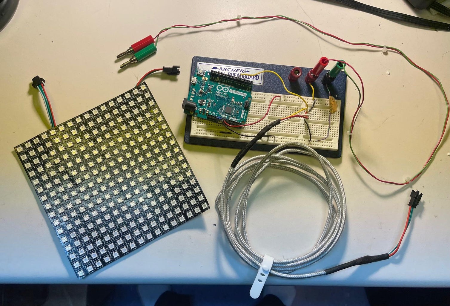
Some wires, connector pins, soldering iron, etc. that you normally need when doing anything with Arduino. Check the picture, everything is there except the power supply. The breadboard is optional.
Step 1: Connections

Make the following connections:
+5V from power supply to Vin on Arduino and +5V pin on the LED array.
Ground from power supply to GND on Arduino and GND on the LED array.
Pin 6 on Arduino to Data In on the LED array. If you use a different pin on Arduino, change the PIN number in the program.
That's it!
I made a cable to connect to the panel so I could place it a few feet away from the Arduino and power supply. For this I used a broken phone charging cable. The wire was broken at the plug end, I cut off the plugs and soldered a connector for the LED panel on one end, and solid wires on the other end that I could plug into the breadboard. Tip: the LED panels sometimes come with connectors that you have to solder on, so just solder one to the Data In connections and use the other one for your connection cable. You don't need a connector on the Data Out side if you have only one array. A phone charging cable is great for this because the +5V and ground wires are heavy enough to handle a few amps of current, plus there are two data wires to use (we only need one).
I taped a piece of white paper to the LED panel to act as a diffuser, as shown in the picture. This is optional.
Step 2: The Program
Install the Arduino IDE if you haven't already (go to arduino.cc).. Download the Adafruit_NeoPixel library and install it in the Arduino/libraries directory.
Open the Arduino IDE and enter the following code:
#include <Adafruit_NeoPixel.h>
// This program displays a scrolling image on a 16x16 LED array or string of arrays.
#define PIN 6 // change to whatever pin you are using to send data to the LED array.
#define N_LEDS 256 // must be (number of pixels per array)*(number of arrays being used)
#define imageRows 16 // the size of the image that is going to be displayed. Height normally 16.
#define imageCols 285 // Change this number depending on the width of your scrolling image.
// number of rows and columns in each LED panel
#define numRows 16
#define numCols 16
Adafruit_NeoPixel strip = Adafruit_NeoPixel(N_LEDS, PIN, NEO_GRB + NEO_KHZ800);
int numPanels = N_LEDS/numRows/numCols;
int offset = numCols*numPanels;
int pixel = 0;
int imageStartCol = 0;
int imageRow = 0;
int imageCol = 0;
int r=0;
int g=0;
int b=0;
// the image data is stored in program memory (flash memory), because there is not enough RAM in an Arduino to store the whole image.
const uint8_t pc[imageRows][imageCols][3] PROGMEM =
#include "bonneFeteDesMeres285x16.h" // write the name of the text file where the image data is stored.
;
void setup() {
strip.begin();
}
void loop() {
offset--;
if (offset < -imageCols) {
offset = numCols*numPanels;
}
pixel = 0;
for(int panel=0; panel<numPanels; panel++) {
imageStartCol = panel*numCols-offset;
imageRow = 0;
for (int y=0; y<numRows/2; y++) {
for (int x=numCols-1; x>=0; x--) {
imageCol = imageStartCol + x;
if ((imageCol < 0) || (imageCol >= imageCols)) {
drawPixel(strip.Color(0, 0, 0)); // Draw black
}
else {
r = int(pgm_read_byte_near(&pc[imageRow][imageCol][0]));
g = int(pgm_read_byte_near(&pc[imageRow][imageCol][1]));
b = int(pgm_read_byte_near(&pc[imageRow][imageCol][2]));
drawPixel(strip.Color(r, g, b)); // Draw image pixel
}
pixel++;
}
imageRow++;
for (int x=0; x<numCols; x++) {
imageCol = imageStartCol + x;
if ((imageCol < 0) || (imageCol >= imageCols)) {
drawPixel(strip.Color(0, 0, 0)); // Draw black
}
else {
r = int(pgm_read_byte_near(&pc[imageRow][imageCol][0]));
g = int(pgm_read_byte_near(&pc[imageRow][imageCol][1]));
b = int(pgm_read_byte_near(&pc[imageRow][imageCol][2]));
drawPixel(strip.Color(r, g, b)); // Draw image pixel
}
pixel++;
}
imageRow++;
}
}
strip.show();
delay(25); // you can change this number to change the scrolling speed. Smaller number will be faster scrolling.
}
static void drawPixel(uint32_t c) {
strip.setPixelColor(pixel , c); // Draw new pixel
}
Step 3: Create Your Text/image
This program basically displays an image on the LED array, scrolling it from right to left. The image must be 16 pixels high (or whatever is the vertical dimension of your LED array) and it can be up to about 500 pixels wide. Why only 500 pixels? This is because the basic Arduinos like Uno and Leonardo have only 32k bytes of memory, and every pixel in the image requires 3 bytes of memory (values for red, green, and blue). So, 3x16x500 = 24,000 bytes. The rest of the program takes about 5k bytes, so this is about all that will fit. The image is stored in the Arduino's program memory (flash memory) not RAM, because the Arduino has only 2k RAM. The PROGMEM command is used to put the data in the program memory.
Use any word processor software (I used WordPad) to create a short message. Make the background black using the highlight feature. It is helpful to add a few spaces at the beginning and end of the message so you have some black area before and after the text. You can make the text any color you want, even make each letter a different color. You can use any font, but bold fonts will probably work better. It is helpful to make the font larger, 24 point or so.
Copy the text and paste it into Paint (or another image editing software). I actually used PrintScreen and pasted that into Paint, then cropped to get just the text. You can add other images like hearts or flowers, if you are going to do that leave space for them when cropping. Make sure the images have black backgrounds, if not you can manually paint the background black. Make the images the same height as the text.
When you are happy with your message, carefully crop as close as you can to the top and bottom of the text. You should now have a wide image that is just the height of your line of text and images.
Click on "Resize and Skew" and select "Pixels", then change the Vertical number to 16. Make a note of the horizontal pixel size, you will need to change the value of imageCols in the program to this number.
Save the image as a PNG file.
Go to https://onlinepngtools.com/convert-png-to-rgb-values and upload the PNG file. Select the options 3D array and Curly brackets, channel delimiter "comma" and group delimiter "comma". This will generate text compatible with Arduino code. Copy the converted text to the clipboard.
Open Notepad and paste the text. Save it as a file "filename.h", in the same directory as your Arduino sketch. In the program, change the file name from "bonneFeteDesMeres285x16.h" to whatever you have named your new file.
After you have made the changes to the program, connect the Arduino to the USB port of your computer and upload the sketch to the Arduino. I always disconnect the Arduino from the power supply and LED strip when I am connecting to my computer. Supposedly the Arduino can handle being connected to two power sources at the same time, but I think this is risky, especially with a high current device such as the LED array connected, why risk damaging your Arduino or your computer.
That's it, you are done! Turn on the power and enjoy the display!


