

Introduction: Control Home Appliances From a Wireless Poster!


Controlling home appliances is just the first thing I thought of doing. The minute the Drum Poster is talking to the Arduino then the possibilities are endless!
To hack the Drum Poster I created a box for my iPhone with built-in LDRs. The LDRs detect a change in colour on the iPhone screen when different points are touched on the poster.
Novalia Drum Poster Hack from michael shorter on Vimeo.
For this hack you will need:
A Drum Poster by Novalia get it here http://www.kickstarter.com/projects/839415566/novalia-drum-poster
An Arduino
8-Channel Relay Module similar to this
Some jumper cables
Some LDRs
Some 10k Resistors
A breadboard
Some Acrylic (roughly a 12cm by 30cm)
An iPhone
Step 1: Turning the Drum Poster On
Making the Drum Poster work is amazingly easy. Firstly stick a battery in the poster. Now download the SwitchBoard App from Novalia. Open it up, click on settings and turn on Revolucion then click 'done'. The app will say it is scanning and then connected.
Now when you touch the different drums on the poster it will activate the different instruments on the app. Easy! I found that if it loses connection you just need to re-start the app and and let it re-connect again.
Step 2: The Hardware


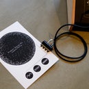
Now lets read the data from the app and send it to the Arduino. To do this I created a box for the iPhone to slide inside with built in LDRs to monitor light levels of the app. Hopefully the image below shows what I am describing....
I have only utilised three of the outputs with three LEDs, but there is scope to hook up eight....
The Illustrator files are available here to allow you to laser cut the box (or alternatively cut and drill). The LDRs are then hot glued into the holes. The LDRs are then connected to the Arduino analog In pins. The Arduino output pins are then connected to the Relay module. You can then wire in any device to the relay module, I wired in three lamps. The relay is wired the same as a switch. ALWAYS BE CAREFUL WITH MAINS, DOUBLE CHECK EVERYTHING!
There is a circuit diagram included in this section.
Below is the Arduino code:
///////////////////////////////////////////////////////////////////////////////////////////////////////////////
int l1 = 13;
int l2 = 12;
int l3 = 11;
int LDR1 = A0; //analog pin 0
int LDR2 = A1;
int LDR3 = A2;
;
// the setup routine runs once when you press reset:
void setup() {
Serial.begin(9600);
// initialize the digital pin as an output.
pinMode(l1, OUTPUT);
pinMode(l2, OUTPUT);
pinMode(l3, OUTPUT);
}
// the loop routine runs over and over again forever:
void loop() {
int LDRReading1 = analogRead(LDR1);
//Serial.print("LDR1 = ");
// Serial.println(LDRReading1);
int LDRReading2 = analogRead(LDR2);
Serial.print("LDR2 = ");
Serial.println(LDRReading2);
int LDRReading3 = analogRead(LDR3);
// Serial.print("LDR3 = ");
//Serial.println(LDRReading3);
delay(250);
if (LDRReading1 < 700){
digitalWrite(l1, LOW);
delay(100);
}
if (LDRReading1 > 700){
digitalWrite(l1, HIGH);
delay(100);
}
if (LDRReading2 > 880){
digitalWrite(l2, LOW);
delay(100);
}
if (LDRReading2 < 880){
digitalWrite(l2, HIGH);
delay(100);
}
if (LDRReading3 > 830){
digitalWrite(l3, LOW);
delay(100);
}
if (LDRReading3 < 830){
digitalWrite(l3, HIGH);
delay(100);
}
}
///////////////////////////////////////////////////////////////////////////////////////////////////////////////
You will have to callibrate the LDR switching value depending on your phone brightness. It is a good idea to put your phone on full brightness and turn any auto-locks off.
Attachments

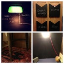
Step 3: Re-Skin the Drum Poster
We can now create our own graphics to go over the drum poster. This can be whatever you like as long as the touch points line up with the touch points on the drum poster. I sketched the three different lights that I was turning on and off.
The beauty of Drum Poster is that it is not only a really cool product but it can be used as a platform to control just about anything!
Enjoy.
M

Participated in the
Remote Control Contest


