

Introduction: Convert Xiaomi NightVision Wireless IP Camera to a Remote Door Viewer


Do you want to avoid answering callers at your front door?
Do you want to interact with them remotely?
Do you want extra security?
KickStarter projects too expensive? Too much Hipster BS?
Want something free? (CC-Attribution)
Well you can 3D print a housing to mount the Xiaomi IP camera with Night Vision (Xiaomi Ants) at your front door! The camera itself cost roughly £20 (US$30?), and you do need some hacking with the hardware, mainly just soldering skills, extra parts required...
Undaunted? Read on!
Bill of Material:
1) Xiaomi NightVsion Wireless IP camera
2) Micro USB breakout board, a specific one, dimension is important! NB: The board is 15x13x1.7mm
3) 4 x 8mm, Countersunk Screw, M3
4) 1 x 30mm, Socket Cap Screw, M3
5) 1x 25mm, Hexagon Stand-off Spacer, M3
6) Almost forgot, 1 x 3mm, M3 screw, preferable flat top to screw Hexagon spacer in place
Item 4 and 5 will depend on your door thickness... e.g. Steel Reinforced Meth Lab
Void Warranty Section You have to enlarge the original Mic opening on the camera to allow wiring
Step 1: Void Warranty

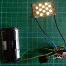
Step 2: Mods and Extend Power Wirings


Identify power terminals coming in from original Micro USB
Solder new wiring for extension, also extend Mic wiring
All wiring will now come out of original Mic hole on camera casing, make this hole bigger to allow access
Bonus: the molex connector that is unconnected has a down regulated output of 3.3V! Could be useful for other things...
Step 3: 3D STL Files...
3D print the housing and door mount...


Step 4:

Fit everything back in... Note position of Mic.
Screw back cover with 4x8mm countersunk M3 screws
Step 5:


It will look like this... thread the wires out, left = negative terminal, right = positive terminal
Add a ring of blu-tak to help mounting on door, for uneven surfaces and avoiding slippage when tightening the screws, much easier to remove than foam double-sided tape
Step 6:


On the back of your door, loop the wire out.
- Thread the wire, noting the correct terminals, and loop securely, no soldering is required
- Now secure your mount with a 30mm M3 screw
- Stuff the excess wiring into the peep hole cavity
- Sit the USB breakout board flush to the mount
- Cap it, that's it, job done!


