

Introduction: Learn Counter ICs Using an Arduino


Have you ever needed to count something? Sure, we all need to count change, count blessings, and occasionally count cards, but that's not really the kind of counting I'm talking about. In this Instructable, I will elucidate how Counting ICs operate, and show how to connect one to a microcontroller so you can see exactly how it works in a controlled way.
Step 1: Why Use Counting ICs?


Yes, yes, why not just use the microcontroller? Arduinos are pretty good at counting things. But what if you want a cheap hardware solution that operates with events as fast as 30MHz? That's what counting chips are for.
My work in the atom optics lab at my university has taken me through some real twists and turns. I've learned more in my two years as an intern there than I have in most of college, and it's way more rewarding than turning in homework. If you ever have the chance to work in a university laboratory, take it, no matter what. You'll never regret it. One of the things I've had to learn pretty thoroughly is electronics, since one of my duties is troubleshooting electronics and occasionally building additions and hacks to them. My most recent project brought me face to face with digital counting ICs.
The project involved using a Michelson Interferometer to compare the relative wavelengths of two lasers by counting the number of fringes of each beam when a retro-reflector cart was translated across the beam paths, thus changing the path lengths of both beams by identical amounts. Light has such a short wavelength that moving the cart even as slowly as a few centimeters per second produces fringe patterns at around 150kHz. The interferometer operation simplifies down to the relation:
λ2=λ1(N2/N1)
where λ is the wavelength of a laser, and N is the number of fringes produced by translating the cart a certain distance. So if we know one laser pretty well, we can find the wavelength of the second laser by counting their fringes. For light being measured by translating the cart over 1 meter, N is going to be around 40 million. Try counting that by hand. No, we need high speed event counting methods.
Another use would be in something like a Geiger counter. If you need to know how much radiation you've been exposed to, you can hook up a traditional Geiger counter to a counter IC and count the number of radiation events, then use the appropriate math to convert the radiation count to rads.
Step 2: Basics of Counter ICs

Counter ICs are a complex configuration of NOR gates. NOR gates are a special combination of (at least) four MOSFETS. NOR gates have two inputs and one output. The inputs and output can be either HIGH or LOW. The output state depends on the input states in the following way:
Source: Wikipedia
| INPUT | OUTPUT | |
|---|---|---|
| A | B | A NOR B |
| 0 | 0 | 1 |
| 0 | 1 | 0 |
| 1 | 0 | 0 |
| 1 | 1 | 0 |
So the output is only HIGH when both inputs are LOW. This is the most basic part of a counter. Each of these NOR gates are paired in a configuration called a "flip-flop". Flip-flops have two inputs (S and R) and two outputs (Q and Q*), and have only two stable states:
| SR latch operation | ||||
|---|---|---|---|---|
| S | R | Action | ||
| 0 | 0 | No Change | ||
| 0 | 1 | Q = 0 | ||
| 1 | 0 | Q = 1 | ||
| 1 | 1 | Restricted combination | ||
The two output states can be chosen between by setting either S or R HIGH. When both inputs are LOW, the flip-flop stores its output state according to whatever input it last received. If we string one of the outputs of one flip-flop to the input of the next flip flop, along with some other necessary connections, then each flip-flop down the line depends on the previous states of the flip-flops before it. The previous states depend on the number of triggering events that the system has received. The first output changes state with each external triggering event, called a clock pulse. The second flip-flop changes state every two clock pulses. The third flip-flop changes state every four clock pulses, and so on, with the number of clock pulses required to change state doubling for each subsequent flip-flop.
But what happened to the other flip-flop output? There were two for each one. In fact, each extra output represents one bit of information. If we were to test the voltages of these outputs after sending the counter a certain number of clock pulses, we would see:
| Clock Pulse | Output |
|---|---|
| 0 | LLL |
| 1 | LLH |
| 2 | LHL |
| 3 | LHH |
| 4 | HLL |
| 5 | HLH |
| 6 | HHL |
| 7 | HHH |
Which is binary code! With this configuration, we can only count 8 different states, but by adding another flip-flop, we could count to 16. With two more, we could count to 32, and so on! The table shows a three bit counter. If we had an 8 bit counter, it could count up to 256, and would be able to store one byte of information! If we string two 8 bit counters together, we can count up to 256*256=65536! Depending on how many events you need to count, you can just string a bunch of counters together and reach the appropriate counting limit. Counters in this configuration are called "ripple counters", since the state of the previous flip-flop ripples along to the next flip-flop. There are many other types of digital counters, but this is the easiest to understand.
Step 3: Get a Counter IC

As I said, there are many different types of counter ICs available, but the simplest ones are ripple counters. Your first counter should be one that has continuous outputs. The first counter I ever had to learn was the obscenely complex 82C54 with 24 pins and 6 bytes of highly controlled storage and required the use of a microcontroller. It had outputs that could only be read when it received a command from the microcontroller, and you don't want that. Maybe later, but not right now. It took me weeks to figure out how to use it. The counting pins should be dedicated and continuously readable by even a voltmeter as the counter does its job. The chip I use in this Instructable is a 74LS161, which is a 4 bit, presettable binary counter. The datasheet available on Mouser is pretty useless. I used this datasheet.
The 74LS161 has 16 pins. Two for power, four for operation control, four for count input, four for count output, one for the clock pulse, and one for the "carry output". I will be using the pinout names from the datasheet linked above (from alldatasheet) from now on.
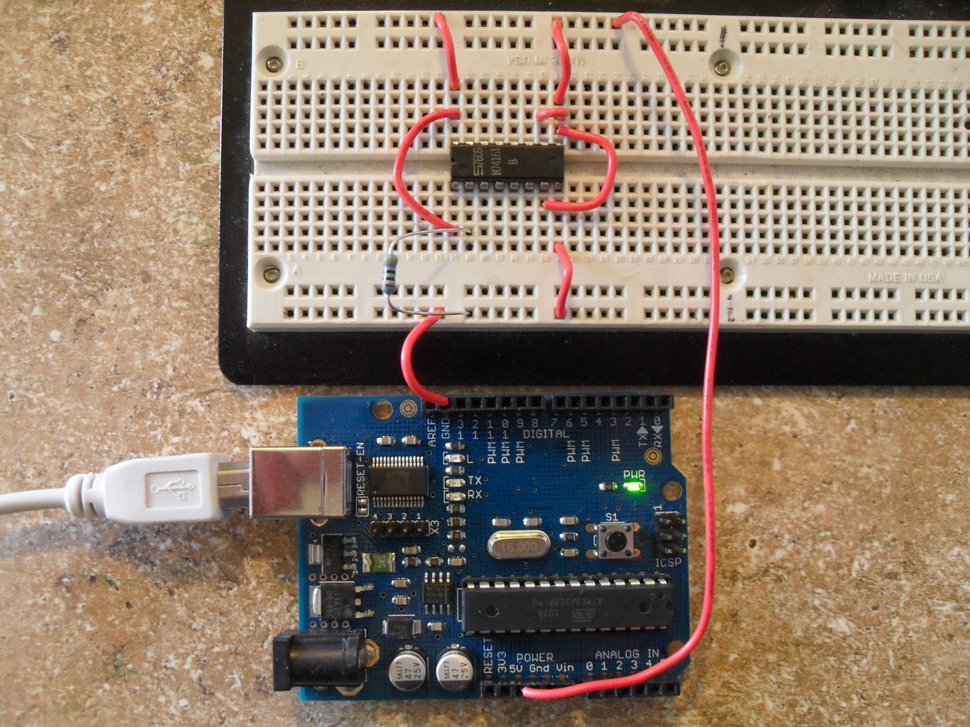
To get the feel for basic counting operation, we just want to tell the chip to count and introduce a steady, slow clock pulse. Place the chip in your breadboard and make the following connections:
Pins 1,7,9,10,16 to +5V.
Pin 8 to ground.
Pin 2 to ground through a 470ohm (or similar) resistor.
Pins 8 and 16 are to power the chip. Pin 1 is the master reset (*R), and resets the count when the signal goes LOW, so we want to keep it HIGH. Pins 7 and 10 (CEP and CET) enable counting when set HIGH. They control subtly different operations, but we don't need to worry about that. Pin 9 (PE) allows you to write to the counter when set LOW, but we just want to count, so set it HIGH. We'll talk about writing later.
The chip is now set to count! whenever the chip detects a "leading edge" on pin 2 (CP, the clock input), it will advance the count by one. A leading edge is the moment when CP detects the signal as HIGH. This is so the count advances right when CP goes HIGH even if CP is held HIGH for a long time.
Before we go on to using the Arduino, test out the chip manually. Use a voltmeter to test the voltages of pins 11-14. These pins are named Q0, Q1, Q2, and Q3. Q0 (pin 14) is the "least significant bit", meaning it changes state with each clock pulse. Q3 is the "most significant bit" meaning it represents the highest order of magnitude for the chip. In this case, if Q3 is HIGH, it means that the chip is storing a number greater than or equal to 8. If you just turned the chip on, then they should all be near zero, but they might not be. Just remember the state that you measured. Now use a wire to connect CP to +5V briefly. This is a very long clock pulse. If there wasn't any noise while you connected the wire, the count should have advanced by one. Measure the output pins again and compare the new state to the old state.
When you read the pins, you can represent the states with a binary number in the following format: Q3,Q2,Q1,Q0. So if the count is one, Q3=0,Q2=0,Q1=0,Q0=1. If the count is 7 (0111 in binary), then Q3=0,Q2=1,Q1=1,Q0=1. To represent the count as a decimal number, use this formula: count = Q0 + 2*Q1 + 4*Q2 + 8*Q3. In all likelihood, there was some noise when you temporarily placed the wire on CP, and the count will be completely different since the chip can respond to signals as fast as 35MHz. But that's ok, we just wanted to see that the counting pins were working. Now it's time for some better control.
Step 4: Reading Bits


The goal in this step is to get the Counter to reliably process individual clock pulses, then have the Arduino read the Counter and display the count.
First we need to make the proper connections between the IC and the Arduino. This is all digital, and the Arduino only has 12 available pins for this sort of thing (pins 0 and 1 are reserved for serial communication). Use the attached image to make your connections. Pin 13 is used for the clock pulse so the Arduino LED blinks whenever a pulse is sent. Once you've made your connections, burn the script attached below to the Arduino, the code is annotated. Once the Arduino is blinking away, open the Serial Monitor and you should see it counting from 0 to 15 over and over again!
Attachments

Step 5: Upgrading the Counting Limit


Pin 15 of the IC is called the Terminal Count, or TC pin. It goes HIGH when the count reaches 15. This is a rather bad design. What this pin is designed to do is carry the value of 16 on to the next counter in the sequence. But if it were designed well, it would simply pulse on the transition between 15 and 0. As it is, the first counter counts to 15, sends the 15 forward to the next chip (which is really representing a 16 on the second chip), and retains the 15 on the first chip for one clock pulse.
| Count | TC | Q0 | Q1 | Q2 | Q3 |
|---|---|---|---|---|---|
| 14 | L | L | H | H | H |
| 15 | H | H | H | H | H |
| 0 | L | L | L | L | L |
This means that when we read off the values from the chips, every 16 clock pulses we will see an erroneous count that is 15 higher than it should be. The number of counts is still ok, but the value that is read from the output pins is wrong every 16 counts. This could be fixed in software, but it's not important here. It's just important to see the limitations of the technology we have at our disposal.
Wire up the chips according to the schematic below. Then burn the attached code and open up the serial monitor. The number should count from 0 to 254, with erroneous numbers displaying every 16 numbers or so.
Attachments
Step 6: Writing Bits


Now that we've got a little bit of control over this chip, let's try writing initial counts. Why would we want to do that? The counter that I used in the lab was a variety that counted down from a specified number, unlike the IC in this Instructable which counts up. If you ever have one of these, then setting a starting count is just like setting a timer. In fact, the counter you have can do the same thing, it just requires an additional subtraction.
Since the arduino only has 12 available pins, we can't do read/write operations on the one byte configuration. We'll have to simplify it down to 4 read/write bits. We want to find an initial count based on the time we want to pass, the period of the clock pulse, and the fact that the counter counts up to 15, and then activates the Terminal Count pin.
Let's say we want 4 seconds to pass, and t=0 is when we want the timer to go off. The period of the clock pulse is around 0.5 second. If a count of 15 represents t=-0 seconds (we're using TC as the activation pin for whatever it is we're doing), then 14 is t=-0.5 seconds, 13 is t=-1.0 seconds, and so on. In general, t=-(15 - count)*T, where T is the period of the clock pulse, and f=1/T for frequency of the clock pulse.
So to count down from 4 seconds before t=0:
-4=-(15 - count)*0.5 ⇒ count = 7 ⇒ count = 0111 in binary. This is the initial count we want to use to have TC go HIGH every 4 seconds.
Pin 9 of the IC is PE, or Parallel Enable. This pin allows you to write bits to the counter when it is held LOW. The bits present on pins 3 through 6 (P0-P3), are then loaded on the next clock pulse. So the order in which you should load bits is:
Hold P0-P3 at the desired number. Set PE LOW. Send clock pulse. Set PE HIGH. The bits are now loaded and the next clock pulse will advance the loaded count by one.
Wire up the Arduino and IC according to the schematic below, burn the attached script, and pull up the serial monitor. You should see the counter counting up from 7 over and over.
Attachments
Step 7: Count All the Things!

Now that you know how to count electronically, you can stop using those pesky fingers! Right? Hmm, maybe not, but if you ever need to count a lot of something very quickly, you now have to tools to do so. Just pick an IC that will do the job and let it do what you're either too lazy or too human to do yourself.

Participated in the
Arduino Challenge


