

Introduction: Custom 3D Printed Anti-Slip Knee Brace


Our client is a happy and active community volunteer who needs a custom knee brace to fit her uniquely-shaped knee. She has undergone many surgeries and has a skin graft on her knee that makes traditional knee braces slide off or not fit well. She has tried all the knee braces on the market, none of which provide the comfort or functionality she requires. Currently, she relies on a walker, but her end goal is to regain independent walking ability.
This Instructable will go through the process we took to create a custom knee brace for our client. The brace is designed to fit her exact measurements while providing necessary support and comfort.
Supplies
Materials
Hinge - We used a hinge from a previous knee brace, but a similar hinge can be ordered. Procare Dual Axis Hinge, 14 1/2" , Procare Dual Axis Hinge, 14 1/2"
ClearWeld Syringe Epoxy Adhesive
Everbilt #8-32 x 1/2 in. Combo Round Head Zinc Plated Machine Screw (8-Pack) 803091 - The Home Depot
3D Printer and Printer Filament
Silicon Lined Foam Pieces from Fusion Women's OA Plus Knee Brace - Silicone Lined Foam (We used pieces from this specific brace, but silicon beading could be used instead)
Hex-nuts
Screws
Tools
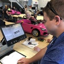
Step 1: Meeting Our Client

The first step of this project was to meet with our client and other team members who would be helping us along the way. This step is extremely important to understand what the client's exact wants and needs are. It is also important to understand who we are working for and why we are doing it.
We discussed what types of knee braces she used and the pros and cons of each. The main issue with all marketed knee braces is that they are uncomfortable and/or do not provide the support she needs because of her skin graft and other injuries.
We also included our client's physical therapist. She explained the mechanics our client's knee and where some of her pain or discomfort could be coming from. She then provided information on previous knee braces and how they work. This part was important because we needed to understand how to make the brace supportive yet comfortable.
Step 2: Research on Knee Braces

Before starting on the design of the knee brace, research was conducted on various topics. This step is crucial not only for understanding how knee braces work but also for comprehending the different types available and the specific parts of the knee they support. For each patient, a different level of support and fit will be needed and those answers will come from research.
Some of the topics our team researched included:
- Structural Materials
- Comfort Materials
- Scanning/Casting
- Skin Grafts
- Movement of the Knee
- Surgeries
- Market Analysis
Some of these topics may not be applicable to every client, or additional research may be necessary based on your discretion.
Step 3: Taking Measurements


Through research and the assistance of a local clinical physical therapist, we identified the specific knee measurements needed to make the custom knee brace fit properly. We took the following measurements:
- Over the Knee Cap = 16.5 inches
- Thigh = 17.75 inches
- Top Patella: 16.75 inches
- Bottom of Patella = 13.25 inches
- Knee Width = 5.0 inches
- Thigh Width = 4.75 inches
- Calf Width = 3.75 inches
- Heel to the bottom of the patella = 18 inches
- Bottom of the patella to the outer hip = 16 inches
These measurements will serve as the basis for designing a 3D model of the knee brace.
Step 4: Plaster Casting


After taking measurements, our clinical physical therapist prepared our client's knee for the plaster cast. Her leg was positioned comfortably yet effectively for the plaster to settle.
This is the process for plaster mold casting:
- A mesh piece of fabric was situated around the area where the cast would be applied
- A silicon hose was placed between the mesh and the skin
- The hose is cut against when removing the plaster to protect the skin
- Dip the plaster strip in warm water
- The plaster strip is laid flat across the knee
- This process is repeated until the entire knee is covered
- Make sure the stips go up and down far enough. They should cover part of the thigh and part of the shin/calf.
- Let the plaster harden
- Once hardened, the plaster is carefully cut off of the knee
- Remember to cut along the silicon hose
- The seam where the plaster was cut is then glued back together using epoxy
- A base was attached to the plaster cast
- A piece of cardboard was measured and cut out
- The piece of cardboard was glued to the bottom of the cast
Then the process of filling the mold with plaster is done next.
- Estimate the volume of the cast to fill with plaster, then fill up a container of water to the respective volume
- Our plaster required a 60:40 ratio when mixing with water, so now prepare the amount of plaster needed to the side.
- slowly sift the plaster into the water container to dissolve evenly.
- Once all plaster is in the mixture, stir by hand or with a plaster mixing tool to ensure air bubbles are not present.
- Once the plaster is no longer a liquid substance and you can make lasting indentations to the surface by dragging your finger across, you may begin pouring the mixture into the mold!
- Once finished pouring the desired amount of material, allow the mixture to cure for 24 hours in a well ventilated area.
Once the mold was settled the plaster was removed off the exterior.
- Soak the entire mold in warm water
- This softens the plaster, so it can be removed
- Once the plaster felt soft to the touch, it was cut and peeled away from the mold
The mold was used for sizing and prototypes.
Step 5: Scanning


This step is NOT REQUIRED, but will provide further information.
After the casting was complete, we used a peel 3D scanner to scan our client's leg. This scan was used primarily for reference.
Scanning process:
- Open software and plug-in scanner to computer and power source.
- Calibrate the scanner with the given reflector plate, and prepare software with details like size (mid), detailing (express), and color (none).
- Position the patient's knee without anything obstructing the scanner's view (have room to scan 1-2 feet above the leg surface) or anything to tangle the scanner's cords.
- Example: if sitting in a chair move away from the table legs and extend the leg as far from the chair as possible. If standing up keep any assistance away from the scanner when it is started.
- Begin scanning
- Press start on the scanner touchscreen and carefully observe the model imaging while scanning to ensure the model is being created.
- Restart the scan if the general shape of the model is not desirable.
- Move forward and delete any unnecessary particles when the scan is to your liking with its general shape. Close any holes that cause the model to not load as a solid.
- After editing export the file as a .stl type for modeling in CAD software.
Step 6: Low-fi Model
This step is NOT REQUIRED but will help design the knee brace before starting the final design
A low-fi model was produced. We started with paper and string to help decide on the shape and mechanisms for the hinge. This step is important because it brings the vision to life at little to no cost. Once the low-fi model is assembled it will either demonstrate the feasibility fo the idea or reveal flaws. If flaws are brought to the surface, then reevaluation will be necessary. We settled on our design using paper and string and were ready to move on to the next step.
Step 7: 3D Print

Using the measurements and mold as reference from step 3 and 4, a 3D model was produced using CAD.
Autodesk Fusion 360 was used for creating 3D models and Bambu Studio was used for converting the models to a format that could be 3D printed.
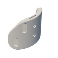
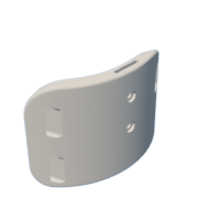
The 3D model for each half of the brace (the specific measurements of each half are slightly different, but the overall process is similar) was created by first sketching two ovals, one larger than the other, and then reducing the outer arc down to 140 degrees. The outer arc was then extruded upward. Some material was removed from a corner of each brace. A slot was created on the top and extruded downward, to create room for the hinge. Channels on both sides of the brace were created for the straps. Holes were added in the middle of the brace for screws to fix the hinge in place. Finally, the corners of the brace were rounded off, to avoid sharp edges.
The following files contain the 3D models generated through CAD, as well as a 3mf file that can be used to 3D print the two models. The 3mf file was created by placing the two 3D models in Bambu Studio, and configuring it for a Bambu Lab P1S printer with an 0.4 mm nozzle, on a textured PEI plate, with basic PLA filament. The nozzle under "Process" is set to 0.20 mm Standard @BBL X1C. All other settings are at their defaults, aside from brim type and brim width under Others. Brim type is set to outer brim only, and brim width is set to 5 mm.

Step 8: Sewing


Pieces of neoprene were cut out to be twice the height of the shape of both the top and bottom parts of the knee brace, with some extra material on the edges to account for the foam pieces that were going to be sewn into them. The next step was to get Velcro strips with adhesive on the backside of it so that they could stick to the brace, with the hooks being on the brace itself and the felt part being sewn into the neoprene pieces by the sewing machine. Another silicone pad was sewn onto the other side of the neoprene to help prevent the brace from slipping down.
Foam pieces were traced and cut out of the high-density foam, placed into the knee brace, and shaved off the excess so that it would be flush when placed into the brace. After the foam was trimmed, they were then sewn into the pieces of neoprene, with 1/4" of seam allowance by using the serger sewing machine.
Velcro straps were also added to keep the brace in place and adjust the tightness. The Velcro straps were modified to secure the brace to the leg by cutting strips of extra Velcro straps to be sewn onto the opposite side of the intended Velcro straps. This was done so that the silicone beaded pads we had acquired could be secured to the straps and have contact with the leg to prevent the brace from slipping.
Step 9: Final Product Assembly and Delivery


Once the 3D print of the knee brace was complete, we checked the size and fit. If your knee brace fits how the customer wants it, please proceed to the next steps.
The hinge was placed into the structure and threaded into the brace with the screws and hex nuts to secure it. The cushions are attached by Velcro onto each thigh and shin brace respectively. The four straps are then slid through the loops with the metal buckle on the front of the leg. After the straps are in, attach the back leg cushion strips to each of the four straps, with the silicone beaded strips on the top and bottom straps.
Now the brace is ready to be used, enjoy!


