

Introduction: Cyber Clock an IoT OLED Desk Clock With Hygro-Thermometer


As a tech enthusiast, I love seeing new technology and inventions. That's why I'm a big fan of Tesla, especially the Cybertruck. I think its design is cool and futuristic. I always wanted to 3D print a small model of the Cybertruck and put it on my desk. Then I thought I could also put an OLED screen as the windshield and build a cool desk clock out of it. The shape of the truck will make this task easy. I started with that small idea and built on top of it. In the end, here is the result,

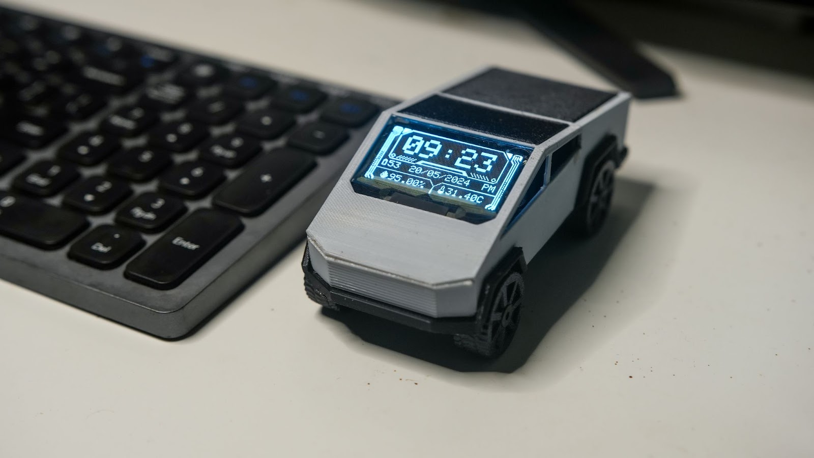
“The Cyber Clock” , A rechargeable battery-powered 1.51-inch transparent OLED clock with accurate internet time and date. It can also measure your room temperature and humidity from an onboard sensor. It can show the battery percentage as well, with a fully 3D-printed Cybertruck body. It also comes with rollable wheels so you can play with it. It is also possible to lock the wheels by tightening screws so it wouldn't fall from the desk by accident !.
also, I would like to mention that I took inspiration from Flipper Zero UI to design this watch face
Through these instructables, we will learn how to build one yourself and customize it to your time zone. so let's get started with the cyber clock build.
Supplies
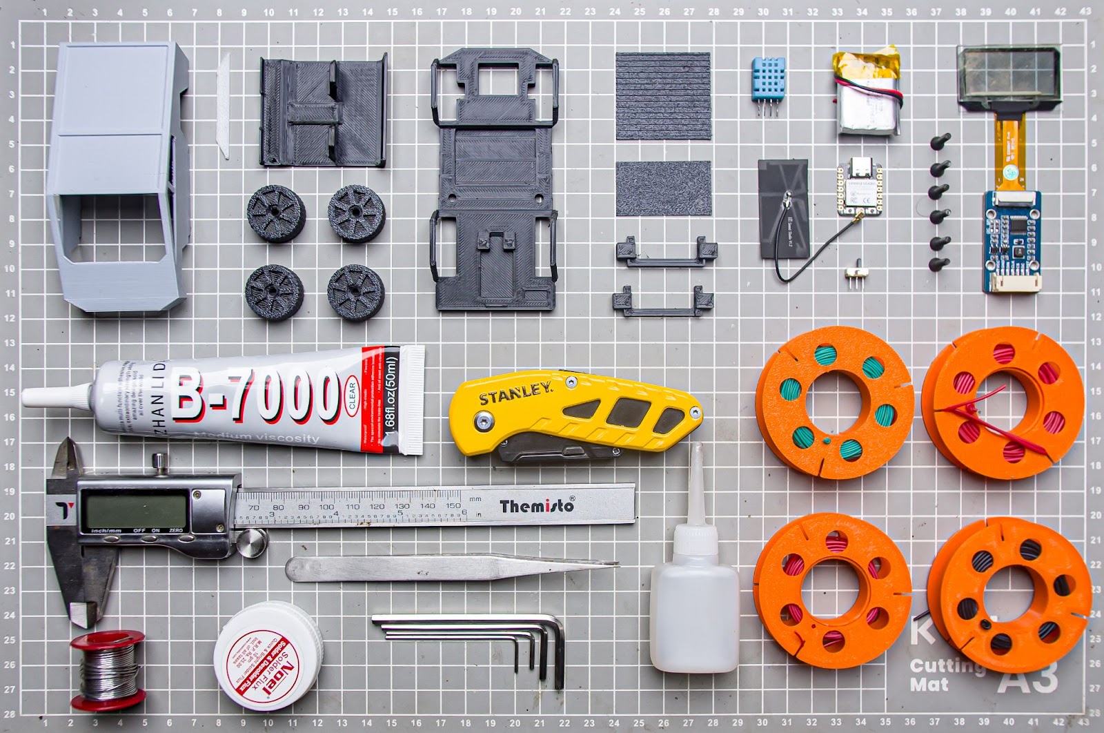
Parts
- Seeed Studio XIAO ESP32C3
- DHT11 Humidity & Temperature Sensor
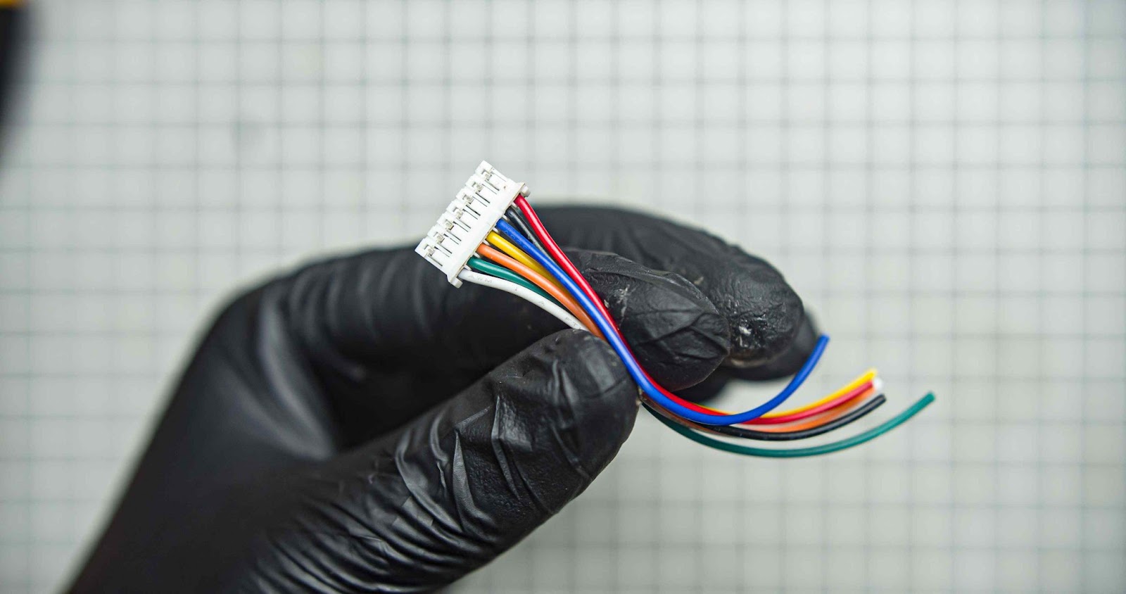
- 1.51inch Transparent OLED you will get JST cable, display, and driver board as a kit
- Slide switch
- 500mah 3.7v battery (identical battery with 600mah)
- 30awg wires
- 6*CSK Allen M3 x 10mm Screws
- B-7000 Multi-Purpose Glue
- Super glue
- Kapton tape 10mm
- 3*10k Resistors ( you can use both SMD type or through hole resistors for it I am using SMD 0805 Resistors for the voltage divider and 10k through hole for pulling up the DHT11 signal )
Tools
- Allen key
- Soldering iron kit
- Wirecutter
- Glue gun
Used 3D printer
Used 3D printing filaments
Step 1: Modeling in Autodesk Fusion 360
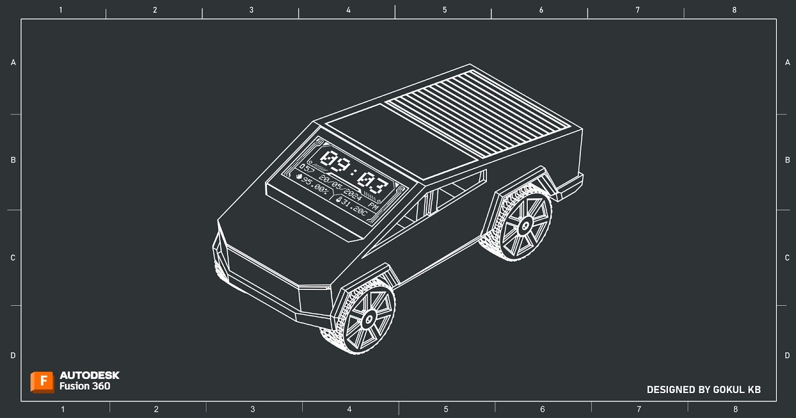
I used Fusion 360 to plan and design my project. I designed this project with two things in mind: easy assembly and 3D printability. I divided the project body into multiple pieces to achieve this. By importing accurate electronic component models, I could pre-determine their positions on the body. This ensured that everything would fit and work together even before I built the prototype, saving a lot of time and effort. All design files are provided below.
Attachments


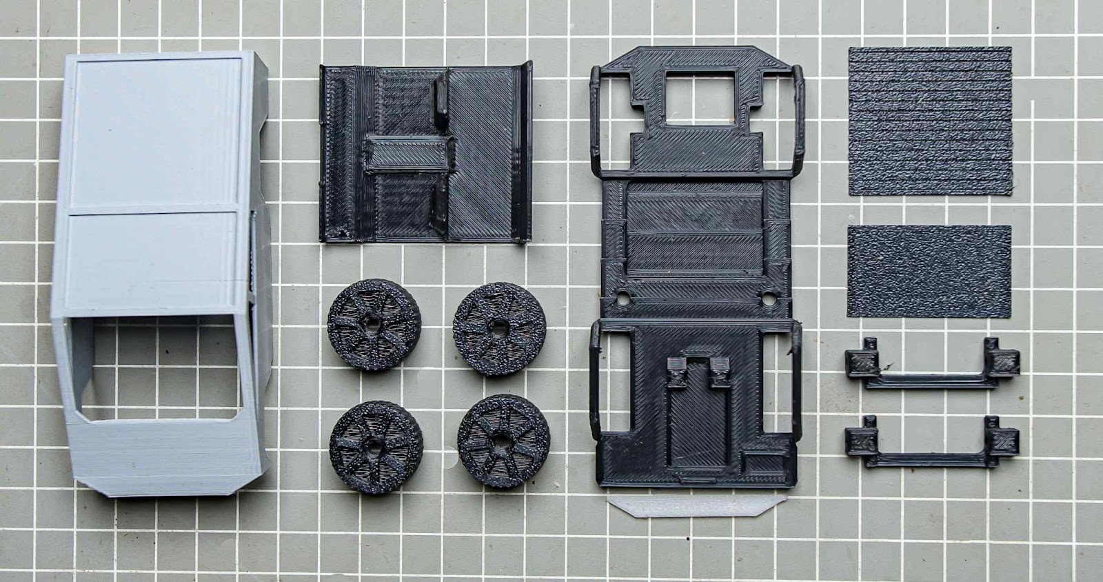
Step 2: 3d Printing
After exporting all the models into.STL files, I 3D printed them using my Anycubic printer. For this project, I used three different coloured PLA filaments: black, grey, and white. You can find the.STL files from step 1. The top body requires some support material when being printed.
Step 3: Flashing Code to Xiao ES32C3
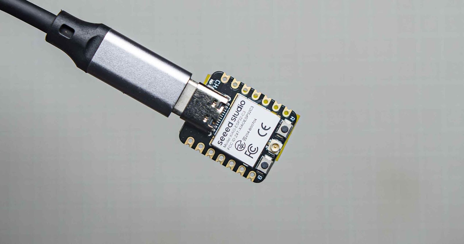
I always like to upload the code to the microcontroller before assembly. I am using Arduino IDE for flashing the code. follow these tutorials for setting up IDE for Seeed Studio XIAO ESP32C3 and learn more about this board
Make sure to install all required libraries into Arduino IDE
libraries for DHT11
How to install library tutorial video link
How to set your wifi password
We need an internal connection to get time data from NTP servers. so we need to connect this clock to your wifi network. you can enter your wifi credentials on 46,47 lines
const char* ssid     = "ssid";
const char* password = "password";
How to set your time zone
The time zone is configured using your GMT offset in seconds. My GMT offset is GMT +5:30, now we need to convert it into seconds which is 19800sec. Just google it for easy conversion
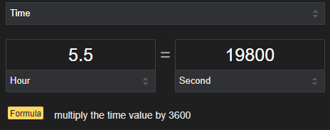
You can enter your GMT offset in seconds in line 65 of the code
NTPClient timeClient(ntpUDP, "pool.ntp.org", 19800, 0);
The complete code
#include <WiFi.h>
#include <SPI.h>
#include <NTPClient.h>
#include <WiFiUdp.h>
#include <Adafruit_GFX.h>
#include <Adafruit_SSD1306.h>
#include <DHT.h>
#define SCREEN_WIDTH 128 // OLED display width, in pixels
#define SCREEN_HEIGHT 64 // OLED display height, in pixels
#define ANALOG_PIN D1      // Analog pin connected to the voltage divider
#define ADC_MAX 4095      // 12-bit ADC
#define REF_VOLTAGE 2.8   // Reference voltage of ADC (3.3V for Xiao ESP32C3)
// WiFi credentials
const char* ssid     = "ssid";//your ssid
const char* password = "password";//your wifi password
// OLED display SPI pins
#define OLED_MOSI    D10
#define OLED_CLK     D8
#define OLED_DC      D4
#define OLED_CS      D7
#define OLED_RESET   D5
Adafruit_SSD1306 display(SCREEN_WIDTH, SCREEN_HEIGHT,
  OLED_MOSI, OLED_CLK, OLED_DC, OLED_RESET, OLED_CS);
#define DHTPIN D0
#define DHTTYPE    DHT11
DHT dht(DHTPIN, DHTTYPE);
// NTP client to get time
WiFiUDP ntpUDP;
NTPClient timeClient(ntpUDP, "pool.ntp.org", 19800, 0);
//bit ui bitmap
static const unsigned char PROGMEM image_paint_1_bits[] = {0x60,0xf0,0x90,0x90,0x90,0x90,0xf0};
static const unsigned char PROGMEM image_paint_0_bits[] = {0x7e,0x3f,0x3f,0xff,0xff,0xff,0xff,0xff,0xff,0xff,0xff,0xff,0xff,0xfc,0xfc,0x7e,0xc1,0x3e,0x40,0x00,0x00,0x00,0x00,0x00,0x00,0x00,0x00,0x00,0x00,0x02,0x7c,0x83,0xd5,0x3c,0x80,0x00,0x00,0x00,0x00,0x00,0x00,0x00,0x00,0x00,0x00,0x01,0x3c,0xab,0xd5,0x39,0x00,0x00,0x00,0x00,0x00,0x00,0x00,0x00,0x00,0x00,0x00,0x00,0x9c,0xab,0xd5,0x32,0x00,0x00,0x00,0x00,0x00,0x00,0x00,0x00,0x00,0x00,0x00,0x00,0x4c,0xab,0x95,0x24,0x00,0x00,0x00,0x00,0x00,0x00,0x00,0x00,0x00,0x00,0x00,0x00,0x24,0xa9,0x25,0x08,0x00,0x00,0x00,0x00,0x00,0x00,0x00,0x00,0x00,0x00,0x00,0x00,0x10,0xa4,0x49,0x10,0x00,0x00,0x00,0x00,0x00,0x00,0x00,0x00,0x00,0x00,0x00,0x00,0x08,0x92,0x93,0x20,0x00,0x00,0x00,0x00,0x00,0x00,0x00,0x00,0x00,0x00,0x00,0x00,0x04,0xc9,0xa6,0x20,0x00,0x00,0x00,0x00,0x00,0x00,0x00,0x00,0x00,0x00,0x00,0x00,0x04,0x65,0xac,0x20,0x00,0x00,0x00,0x00,0x00,0x00,0x00,0x00,0x00,0x00,0x00,0x00,0x04,0x35,0xa8,0x20,0x00,0x00,0x00,0x00,0x00,0x00,0x00,0x00,0x00,0x00,0x00,0x00,0x04,0x15,0xa8,0x20,0x00,0x00,0x00,0x00,0x00,0x00,0x00,0x00,0x00,0x00,0x00,0x00,0x04,0x15,0xa8,0x20,0x00,0x00,0x00,0x00,0x00,0x00,0x00,0x00,0x00,0x00,0x00,0x00,0x04,0x15,0xa8,0x20,0x00,0x00,0x00,0x00,0x00,0x00,0x00,0x00,0x00,0x00,0x00,0x00,0x04,0x15,0xa8,0x20,0x00,0x00,0x00,0x00,0x00,0x00,0x00,0x00,0x00,0x00,0x00,0x00,0x04,0x15,0xa8,0x20,0x00,0x00,0x00,0x00,0x00,0x00,0x00,0x00,0x00,0x00,0x00,0x00,0x04,0x15,0xa8,0x20,0x00,0x00,0x00,0x00,0x00,0x00,0x00,0x00,0x00,0x00,0x00,0x00,0x04,0x15,0xa8,0x20,0x00,0x00,0x00,0x00,0x00,0x00,0x00,0x00,0x00,0x00,0x00,0x00,0x04,0x15,0xa8,0x20,0x00,0x00,0x00,0x00,0x00,0x00,0x00,0x00,0x00,0x00,0x00,0x00,0x04,0x15,0xa8,0x20,0x00,0x00,0x00,0x00,0x00,0x00,0x00,0x00,0x00,0x00,0x00,0x00,0x04,0x15,0xa8,0x20,0x00,0x00,0x00,0x00,0x00,0x00,0x00,0x00,0x00,0x00,0x00,0x00,0x04,0x15,0xa8,0x20,0x00,0x00,0x00,0x00,0x00,0x00,0x00,0x00,0x00,0x00,0x00,0x00,0x04,0x15,0xa8,0x20,0x00,0x00,0x00,0x00,0x00,0x00,0x00,0x00,0x00,0x00,0x00,0x00,0x04,0x15,0xa8,0x20,0x00,0x00,0x00,0x00,0x00,0x00,0x00,0x00,0x00,0x00,0x00,0x00,0x04,0x15,0xa8,0x20,0x00,0x00,0x00,0x00,0x00,0x00,0x00,0x00,0x00,0x00,0x00,0x00,0x04,0x15,0xa8,0x20,0x00,0x00,0x00,0x00,0x00,0x00,0x00,0x00,0x00,0x00,0x00,0x00,0x04,0x15,0xa8,0x20,0x00,0x00,0x00,0x00,0x00,0x00,0x00,0x00,0x00,0x00,0x00,0x00,0x04,0x15,0xa8,0x20,0x00,0x00,0x00,0x00,0x00,0x00,0x00,0x00,0x00,0x00,0x00,0x00,0x04,0x15,0xa8,0x20,0x00,0x00,0x00,0x00,0x00,0x00,0x00,0x00,0x00,0x00,0x00,0x00,0x04,0x15,0xa8,0x20,0x00,0x00,0x00,0x00,0x00,0x00,0x00,0x00,0x00,0x00,0x00,0x00,0x04,0x15,0xa8,0x26,0x04,0x92,0x48,0x3f,0xff,0xff,0xff,0xff,0xfc,0x12,0x49,0x20,0x64,0x15,0x88,0x29,0x09,0x24,0x90,0x7f,0xff,0xff,0xff,0xff,0xfe,0x09,0x24,0x90,0x94,0x11,0xa8,0x29,0x12,0x49,0x20,0xf0,0x00,0x00,0x00,0x00,0x0f,0x04,0x92,0x48,0x94,0x15,0x88,0x26,0x24,0x92,0x41,0xe0,0x00,0x00,0x00,0x00,0x07,0x82,0x49,0x24,0x64,0x11,0xa8,0x10,0x00,0x00,0x03,0xff,0xff,0xff,0xff,0xff,0xff,0xc0,0x00,0x00,0x08,0x15,0x88,0x0f,0xff,0xff,0xfc,0x00,0x00,0x00,0x00,0x00,0x00,0x3f,0xff,0xff,0xf0,0x11,0xa8,0x00,0x00,0x00,0x00,0x00,0x00,0x00,0x00,0x00,0x00,0x00,0x00,0x00,0x00,0x15,0x88,0x00,0x00,0x00,0x00,0x00,0x00,0x00,0x00,0x00,0x00,0x00,0x00,0x00,0x00,0x11,0xa8,0x00,0x00,0x00,0x00,0x00,0x00,0x00,0x00,0x00,0x00,0x00,0x00,0x00,0x00,0x15,0x88,0x00,0x00,0x00,0x00,0x00,0x00,0x00,0x00,0x00,0x00,0x00,0x00,0x00,0x00,0x11,0x28,0x00,0x00,0x00,0x00,0x00,0x00,0x00,0x00,0x00,0x00,0x00,0x00,0x00,0x00,0x14,0xa8,0x00,0x00,0x00,0x00,0x00,0x00,0x00,0x00,0x00,0x00,0x00,0x00,0x00,0x00,0x15,0x28,0x00,0x00,0x00,0x00,0x00,0x00,0x00,0x00,0x00,0x00,0x00,0x00,0x00,0x00,0x14,0xa8,0x00,0x00,0x00,0x00,0x00,0x00,0x00,0x00,0x00,0x00,0x00,0x00,0x00,0x00,0x15,0x28,0x00,0x00,0x00,0x00,0x00,0x00,0x00,0x00,0x00,0x00,0x00,0x00,0x00,0x00,0x14,0xa8,0x00,0x00,0x00,0x00,0x00,0x00,0x00,0x00,0x00,0x00,0x00,0x00,0x00,0x00,0x15,0x28,0x00,0x00,0x00,0x00,0x00,0x00,0x00,0x00,0x00,0x00,0x00,0x00,0x00,0x00,0x14,0xa8,0x00,0x00,0x00,0x00,0x00,0x00,0x00,0x00,0x00,0x00,0x00,0x00,0x00,0x00,0x15,0x2f,0xff,0xff,0xff,0xff,0xff,0xff,0xf0,0x01,0xff,0xff,0xff,0xff,0xff,0xff,0xf4,0xa8,0x00,0x00,0x00,0x00,0x00,0x00,0x08,0x02,0x00,0x00,0x00,0x00,0x00,0x00,0x15,0xa8,0x00,0x00,0x00,0x00,0x00,0x00,0x04,0x04,0x00,0x00,0x00,0x00,0x00,0x00,0x15,0xa8,0x00,0x80,0x00,0x00,0x00,0x00,0x02,0x08,0x20,0x00,0x00,0x00,0x00,0x00,0x15,0xa8,0x01,0xc0,0x00,0x00,0x00,0x00,0x01,0x10,0x50,0x00,0x00,0x00,0x00,0x00,0x15,0xa8,0x02,0xe0,0x00,0x00,0x00,0x00,0x00,0xa0,0x50,0x00,0x00,0x00,0x00,0x00,0x15,0xa8,0x03,0xe0,0x00,0x00,0x00,0x00,0x00,0x40,0x50,0x00,0x00,0x00,0x00,0x00,0x15,0xa8,0x05,0xf0,0x00,0x00,0x00,0x00,0x00,0x40,0x50,0x00,0x00,0x00,0x00,0x00,0x15,0xa8,0x05,0xf0,0x00,0x00,0x00,0x00,0x00,0x40,0x88,0x00,0x00,0x00,0x00,0x00,0x15,0xa8,0x03,0xe0,0x00,0x00,0x00,0x00,0x00,0x40,0xf8,0x00,0x00,0x00,0x00,0x00,0x15,0xac,0x01,0xc0,0x00,0x00,0x00,0x00,0x00,0x40,0xf8,0x00,0x00,0x00,0x00,0x00,0x35,0xa6,0x00,0x00,0x00,0x00,0x00,0x00,0x00,0x40,0x70,0x00,0x00,0x00,0x00,0x00,0x65,0xa3,0x00,0x00,0x00,0x00,0x00,0x00,0x00,0x40,0x00,0x00,0x00,0x00,0x00,0x00,0xc5,0x91,0x00,0x00,0x00,0x00,0x00,0x00,0x00,0x40,0x00,0x00,0x00,0x00,0x00,0x00,0x89,0x49,0x00,0x00,0x00,0x00,0x00,0x00,0x00,0x40,0x00,0x00,0x00,0x00,0x00,0x00,0x92};
float readBatteryVoltage() {
  int analogValue = analogRead(ANALOG_PIN);
  float voltage = (analogValue / (float)ADC_MAX) * REF_VOLTAGE;
  // Voltage divider scaling
  voltage = voltage * (10.5 + 10) / 10.0; // (R1 + R2) / R2
  return voltage;
}
// Function to calculate battery percentage
float calculateBatteryPercentage(float voltage) {
  float percentage;
  // Assuming a linear relationship between voltage and percentage
  if (voltage >= 4.2) {
    percentage = 100.0;
  } else if (voltage <= 2.5) {
    percentage = 0.0;
  } else {
    percentage = (voltage - 2.5) / (4.2 - 2.5) * 100.0;
  }
  return percentage;
}
void setup() {
  // Start serial communication
  Serial.begin(115200);
  dht.begin();
  analogReadResolution(12); // Set ADC resolution to 12-bit
  // Initialize OLED display
  if(!display.begin(SSD1306_SWITCHCAPVCC)) {
    Serial.println(F("SSD1306 allocation failed"));
    for(;;); // Don't proceed, loop forever;
  }
  //display.display();
  // Connect to Wi-Fi
  WiFi.begin(ssid, password);
  while (WiFi.status() != WL_CONNECTED) {
    delay(1000);
    Serial.println("Connecting to WiFi...");
  }
  Serial.println("Connected to WiFi");
  // Initialize time client
  timeClient.begin();
}

void loop() {

  // Update time from NTP server
  timeClient.update();
  unsigned long epochTime = timeClient.getEpochTime();
  struct tm *ptm = gmtime ((time_t *)&epochTime);
  int monthDay = ptm->tm_mday;
  int currentMonth = ptm->tm_mon+1;
  int currentYear = ptm->tm_year+1900;
  int currentHour = ptm->tm_hour;
  int currentMinute = ptm->tm_min;
  int currentSecond = ptm->tm_sec;
 float batteryVoltage = readBatteryVoltage();
  float batteryPercentage = calculateBatteryPercentage(batteryVoltage);
  // Get temperature and humidity
float t = dht.readTemperature();
  float h = dht.readHumidity();

  // Convert time to 12-hour format
  String period = "AM";
  if (currentHour >= 12) {
    period = "PM";
    if (currentHour > 12) {
      currentHour -= 12;
    }
  } else if (currentHour == 0) {
    currentHour = 12;
  }

  // Display data on OLED
  display.clearDisplay();
  display.setTextColor(SSD1306_WHITE);
  // Display time
  display.setCursor(19,6);
  display.setTextSize(3);
  if (currentHour < 10) display.print('0');
  display.print(currentHour);
  display.print(':');
  if (currentMinute < 10) display.print('0');
  display.print(currentMinute);
  display.setTextSize(1);
  display.setCursor(108, 39);
  display.print(period);
  // Display date
  display.setCursor(36, 39);
  if (monthDay < 10) display.print('0');
  display.print(monthDay);
  display.print('/');
  if (currentMonth < 10) display.print('0');
  display.print(currentMonth);
  display.print('/');
  display.print(currentYear);
  // Display temperature
  display.setCursor(79, 53);
  display.print(t);
  display.print("C");
  // Display humidity
  display.setCursor(22, 53);
  display.print(h);
  display.print("%");
  display.drawBitmap(0, 0, image_paint_0_bits, 128, 64, 1);
  display.setCursor(14, 39);
  display.print(batteryPercentage,0);
  display.drawBitmap(8, 39, image_paint_1_bits, 4, 7, 1);
  display.display();
  // Delay before the next update
  delay(1000);
}
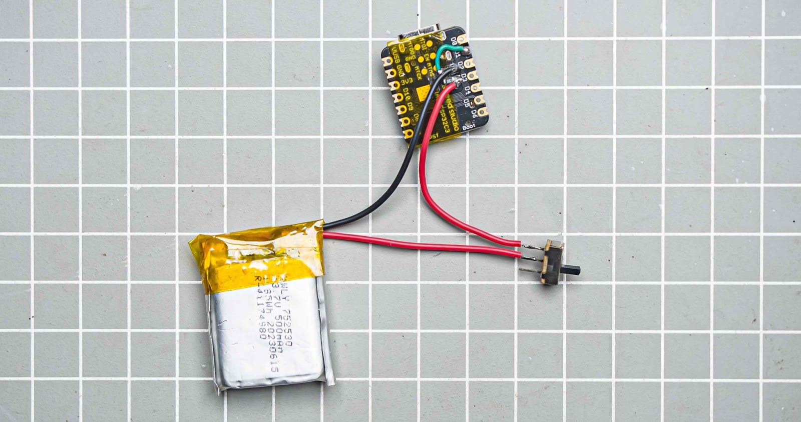
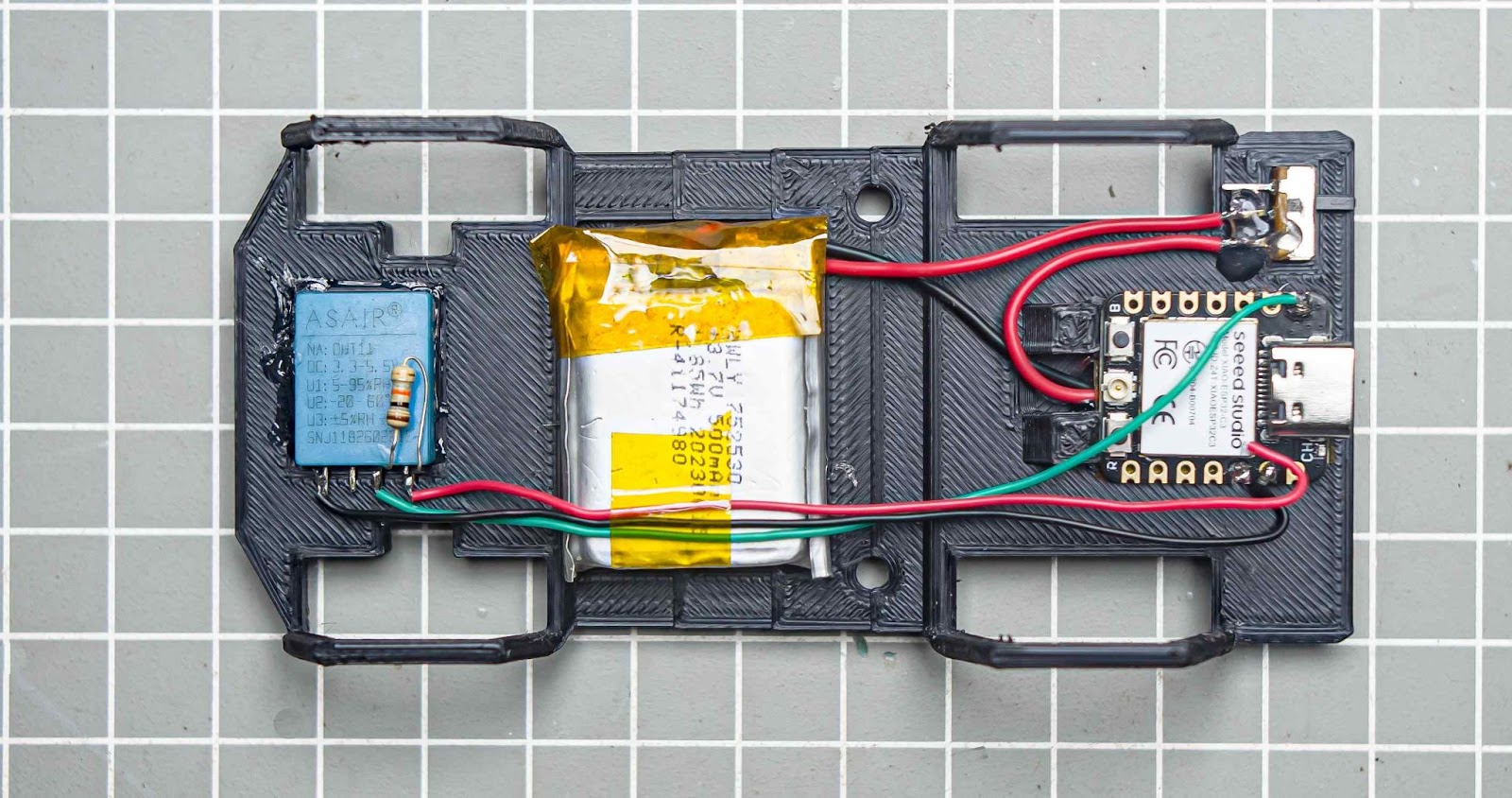
Step 4: Wiring Diagram
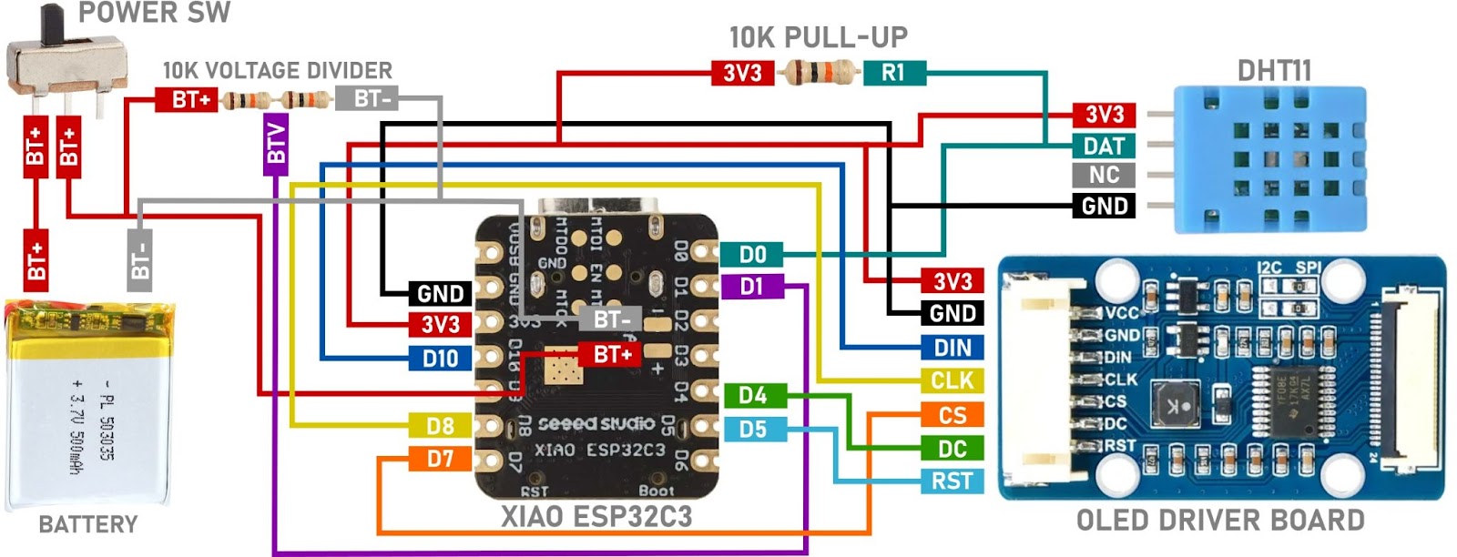
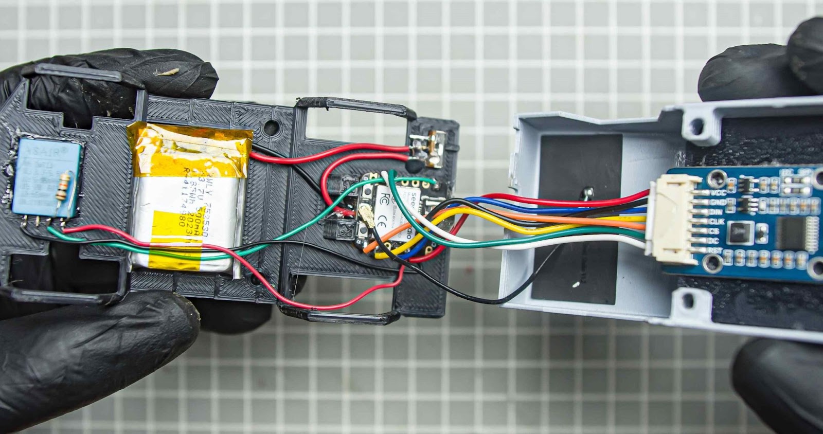
It seems like the wiring is a little complicated right? but just follow the colours of the wire connection and the labels on the endpoints. also, the wire colours used on the driver board and schematic are the same So grab your tools let's start the build
XIAO ESP32C3 Supports lithium battery charge and discharge management . Which means BMS is built in . So there is no need for an external BMS. You can charge the battery through USB port
Step 5: Assembly and Wiring
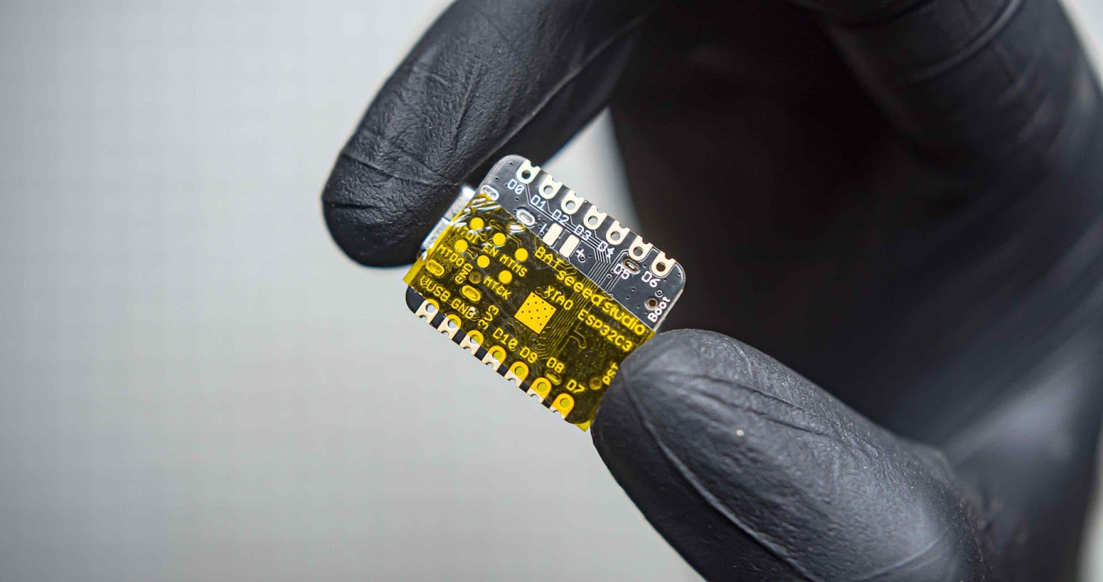
We can start by creating a voltage divider in the back side of the Xiao
Step 5.1
First, we need to put some Kapton tape under the Xiao battery terminate
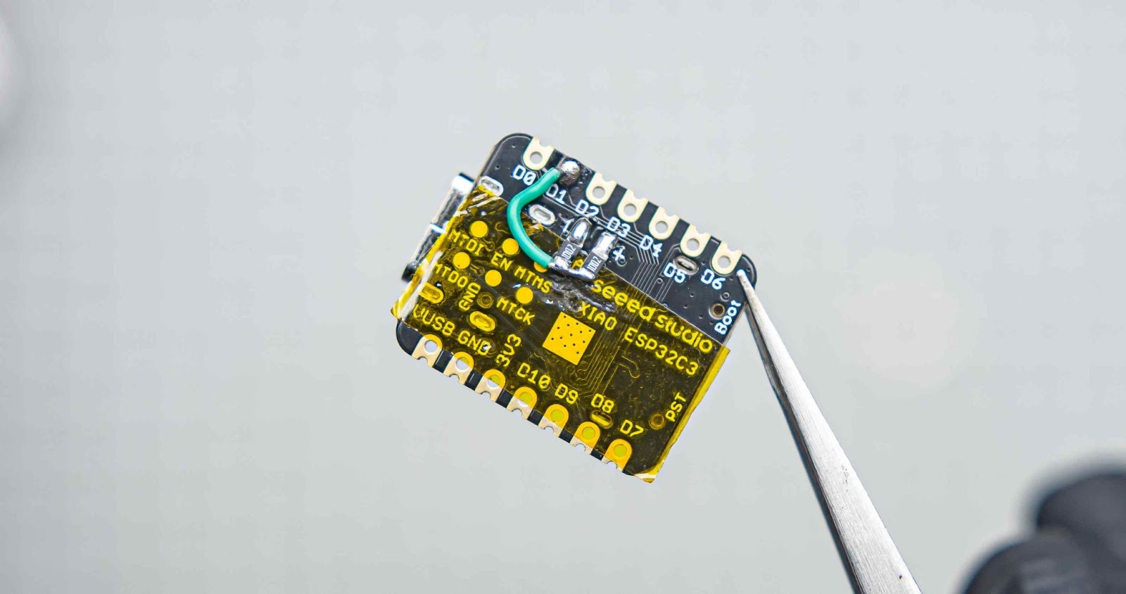
Step 5.2
Solder the 10k SMD resistors to the two battery inputs. Then, connect the other ends of the resistors to the D1 pin using a small gauge wire to measure the battery voltage.
Step 5.3
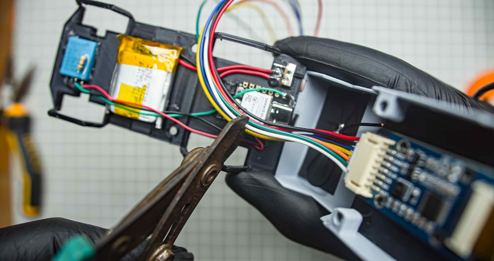
Connect the positive terminal of the battery to one of the terminals of the power switch, and connect the other terminal of the switch to the BAT+ of the Xiao. Also, connect the negative terminal of the battery directly to the BAT- of the Xiao. also, make sure that all the wires are at the proper length by placing them in the underframe
Step 5.4
Glue the battery, xiao, and power switch using glue. I already designed slots for the components to fit in. Make sure to get the wire under the xiao through the gap.

Step 5.5
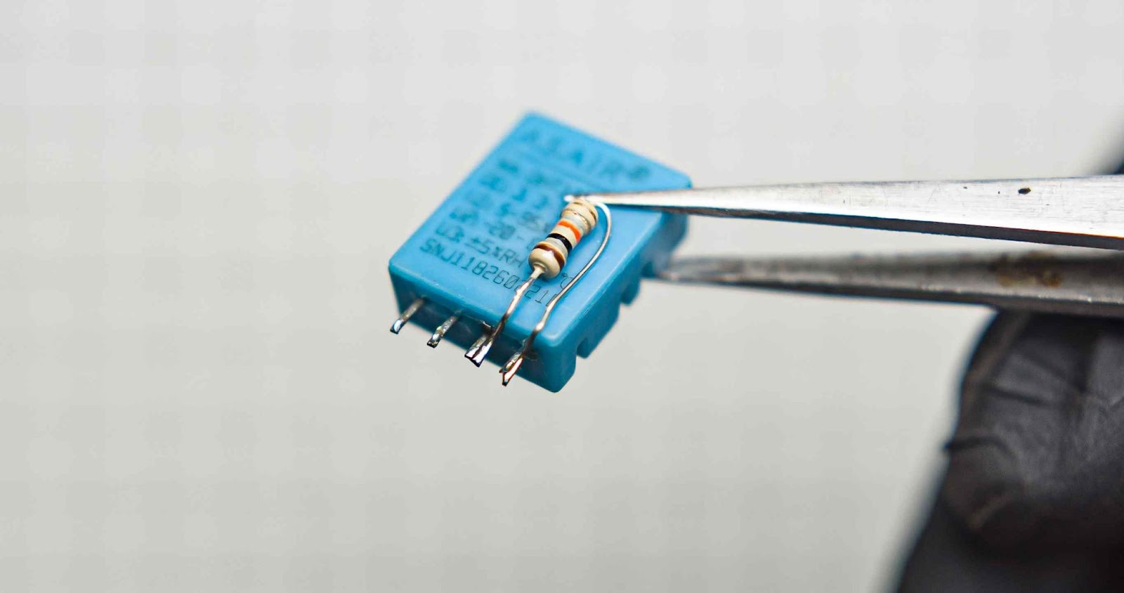
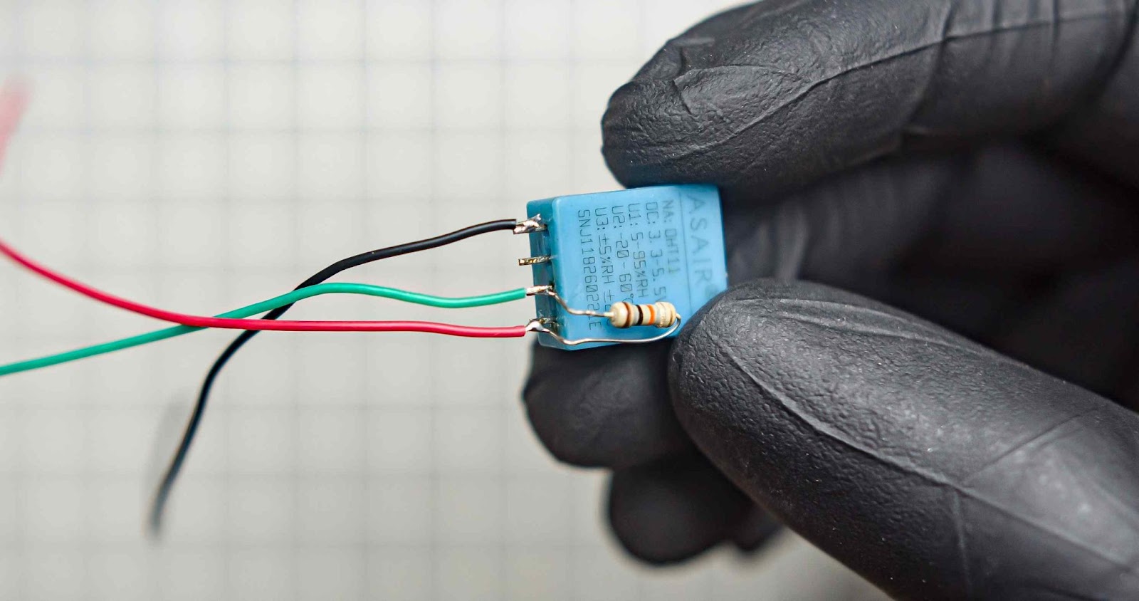
Cut the terminals of the DHT11 to the appropriate length. Solder a 10k resistor between the VCC and DATA lines of the DTH11. Also, solder 3 wires to VCC, GND, and DATA with the length that can reach the Xiao pins. I am using a through-hole 10k resistor here
Step 5.6
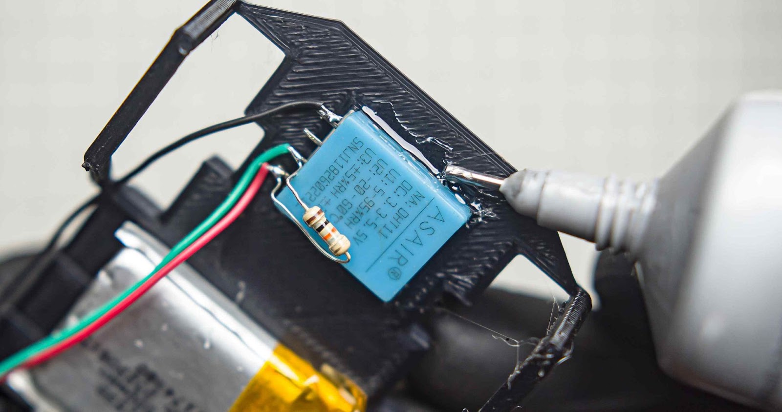
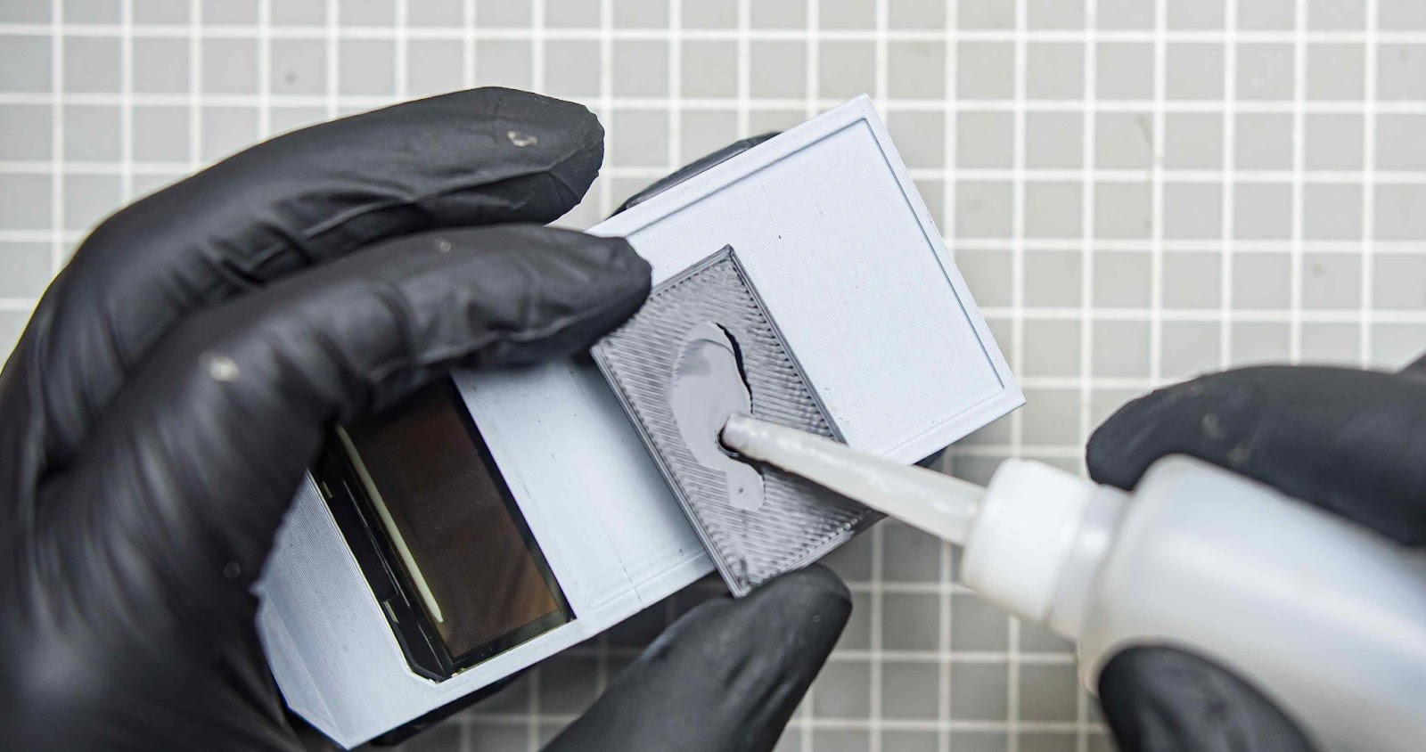
Place the DHT11 upside down into the small window. Now, glue the DHT11 using our B-7000 Multi-Purpose Glue. (We are not using hot glue here because the heat might damage the sensor.)
Step 5.7
Solder the DHT11 sensor wires into Xiao, Also I did some wire management with Kapton tape. now we are done with most of the work on the down frame let's move on to the upper body
Step 5.8
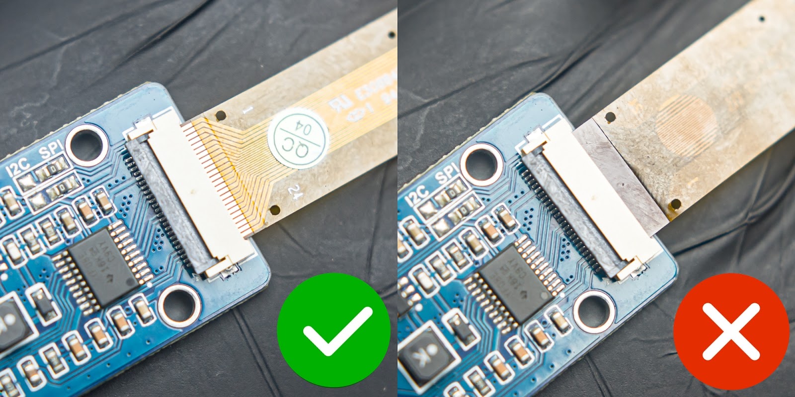
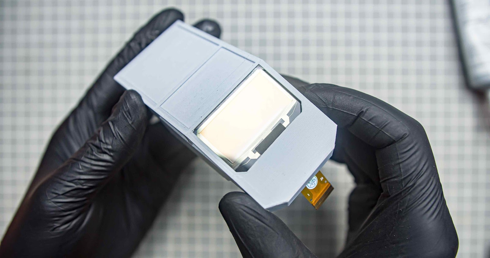
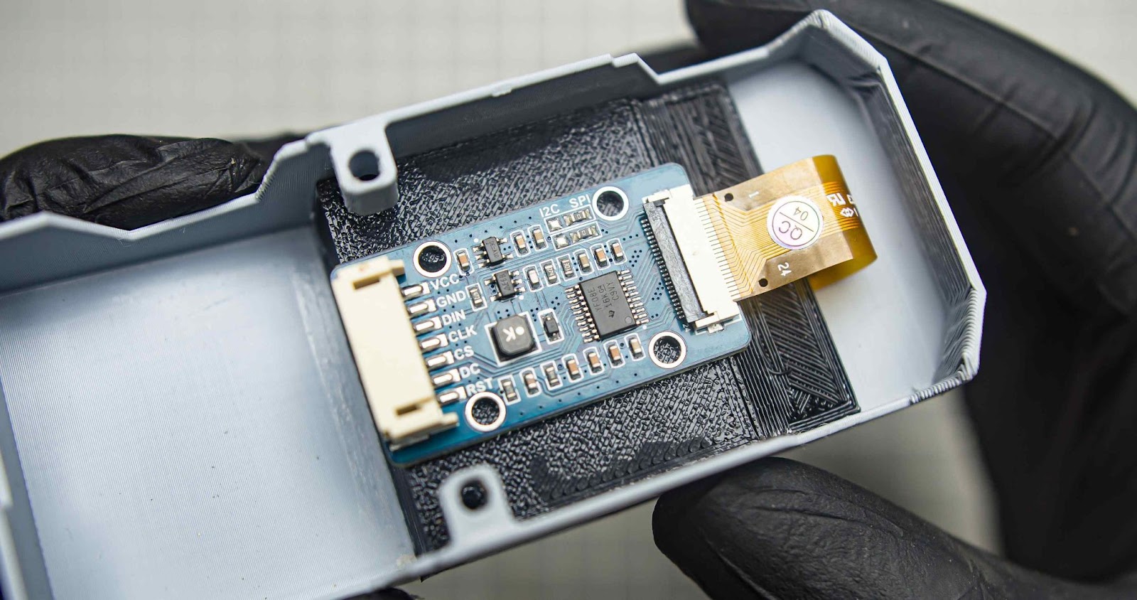
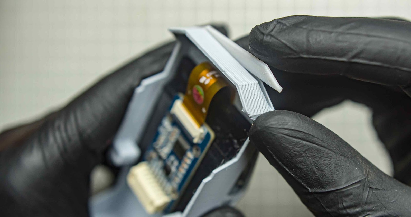
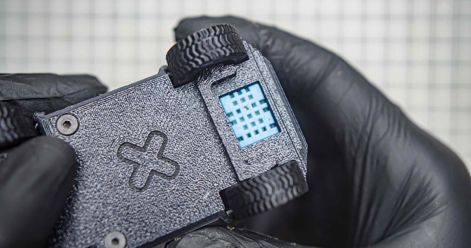
Be very careful during this step as we install the OLED screen into the main body. Do not apply too much pressure when handling the display, as it can easily break. We will be using B-7000 Multi-Purpose Glue to attach the display to the 3D print. Make sure that the orientation of the display is correct.
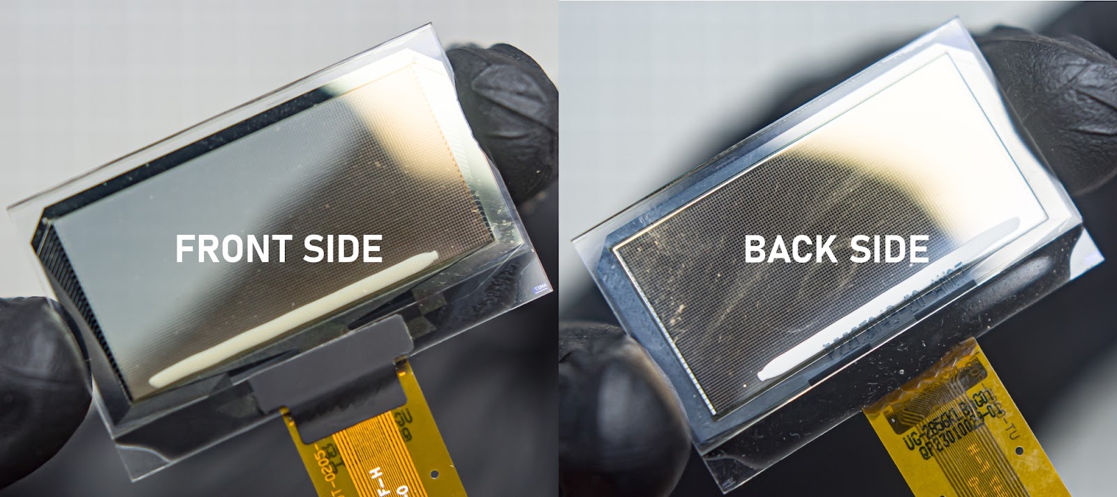
Make sure to check the orientation of the flex cable when you test the display with the driver board.
apply glue to the inside, bottom, and left and right corners of the frame. Don't use too much glue it will spill from the edges
Now carefully place the display into the frame also make sure the orientation is right.
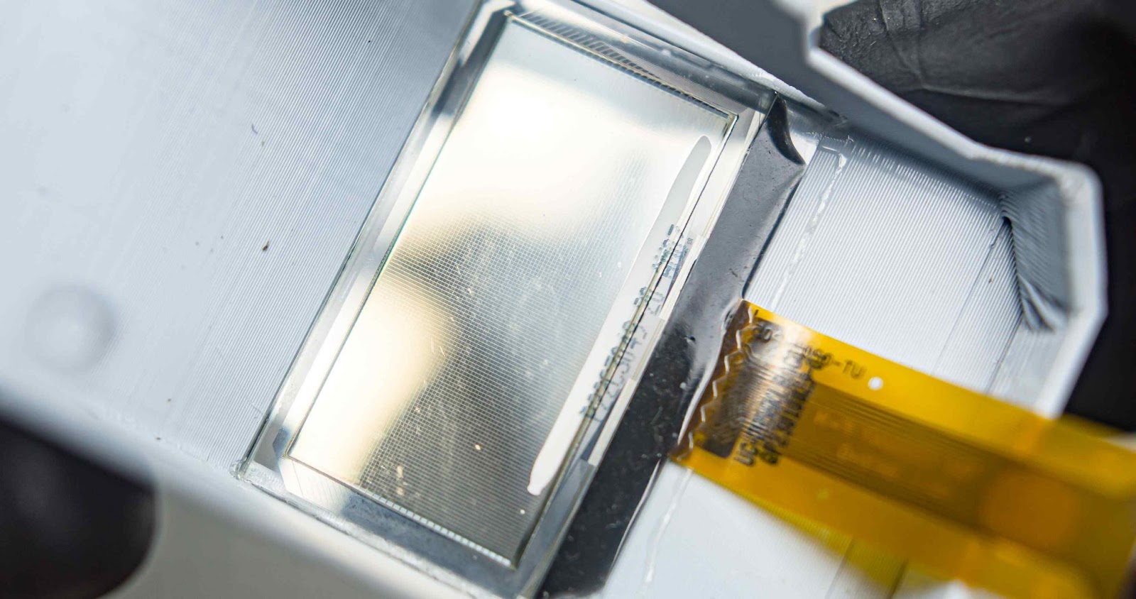
Leave the glue to dry for 20 minutes.
Step 5.9
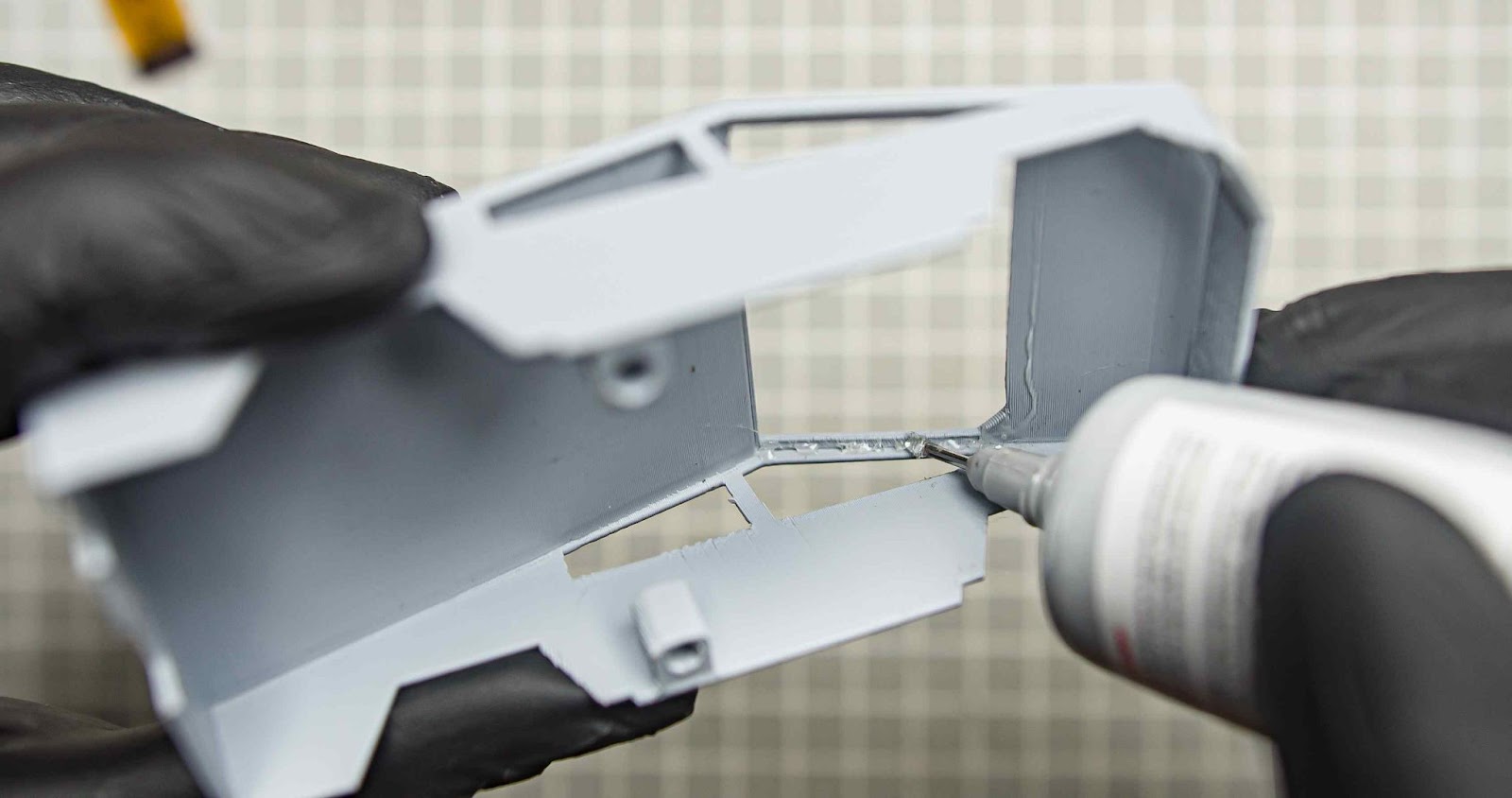
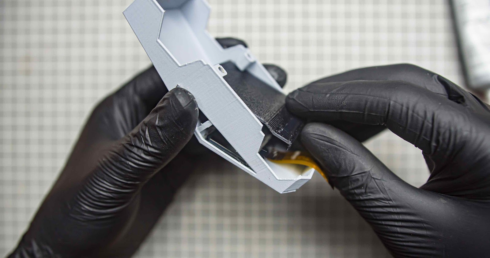
Put the car interior inside the main body and glue it with superglue
Step 5.10
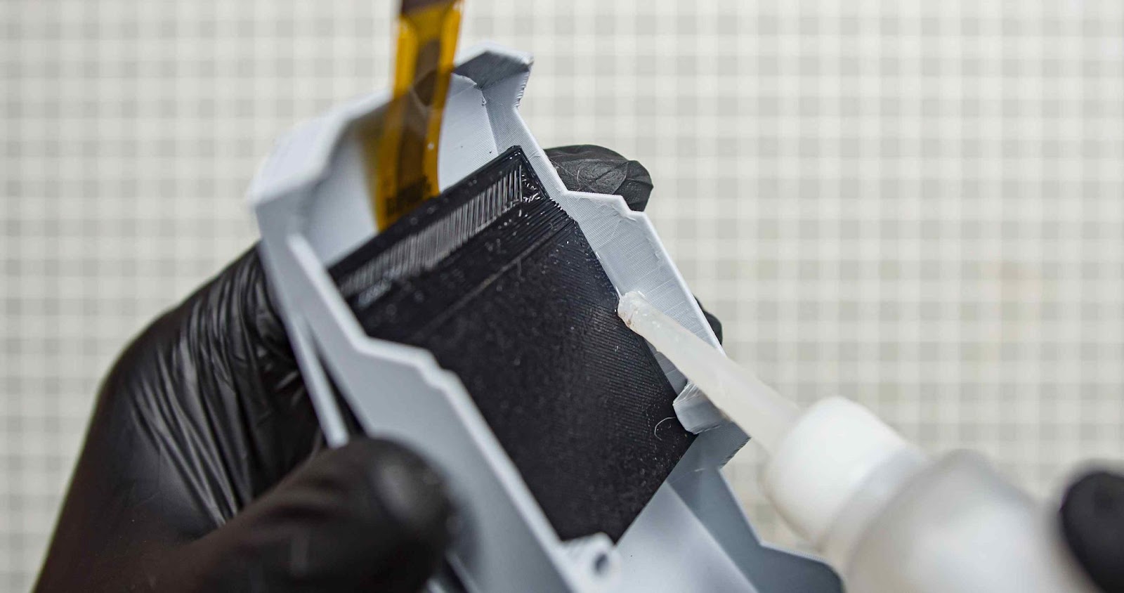
Glue the OLED driver board in the back side of the interior body and connect the flux cable
Step 5.11
Now push in the light bar 3d print in the little gap on the front. You can glue it if you need
Step 5.12
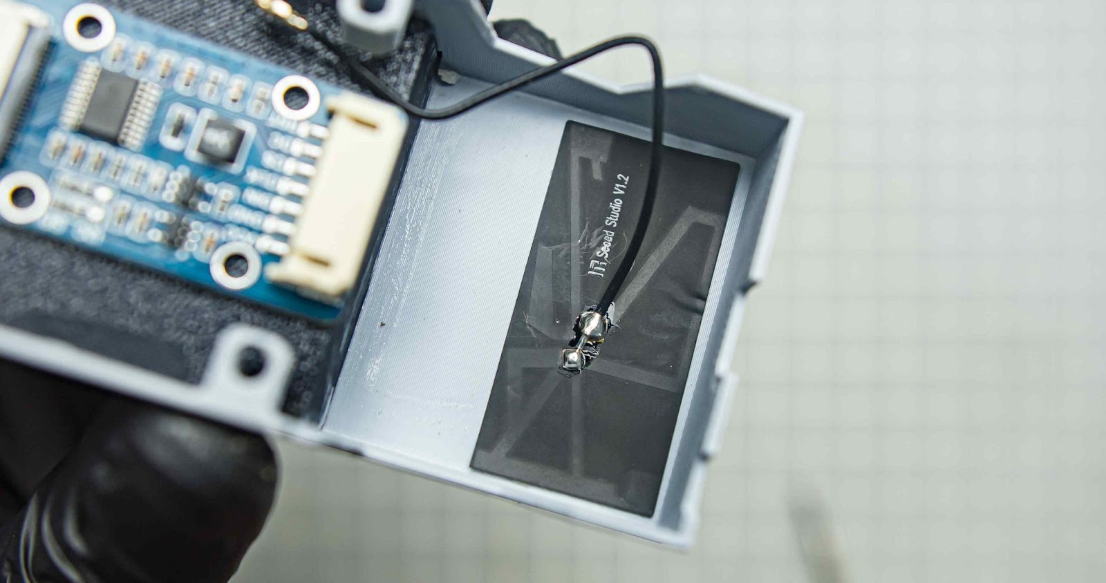
Glue the Xiao esp32 antenna inside the body
Step 5.13
Connect the JST connector and Cut the display driver wires to the appropriate length, then solder them to the Xiao. also connect the antenna port.
Step 5.14
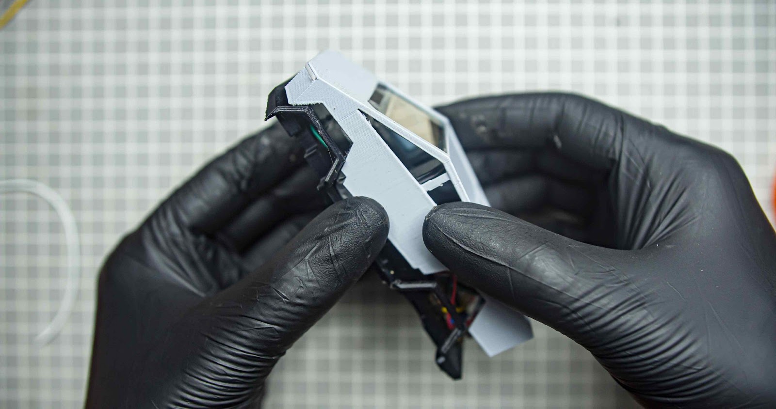
Put the upper body into the underframe and screw it with two M3 screws.
Step 5.15
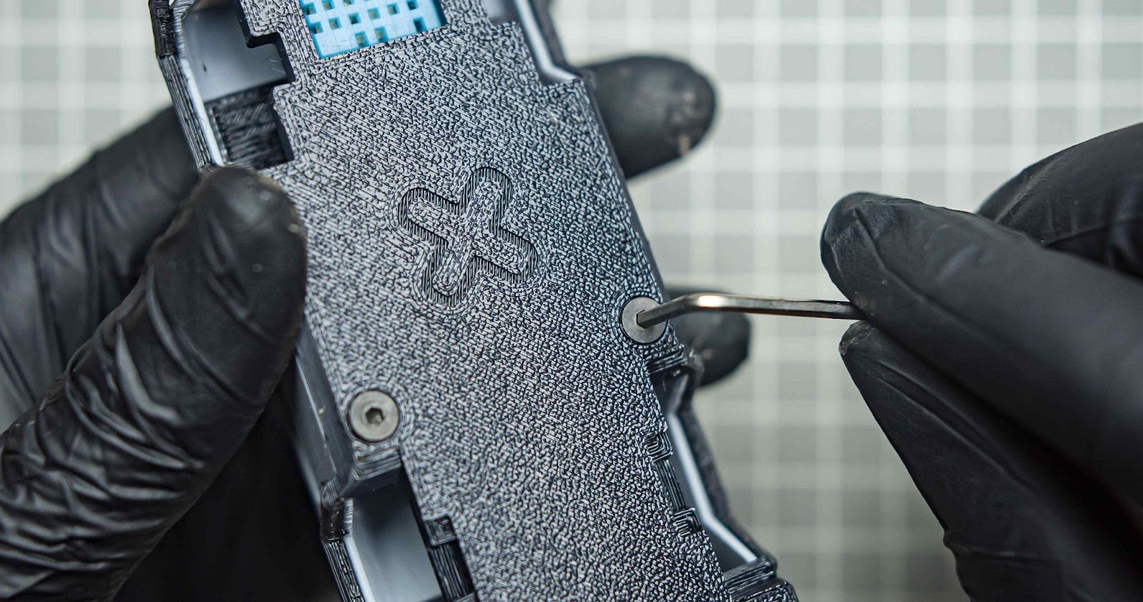
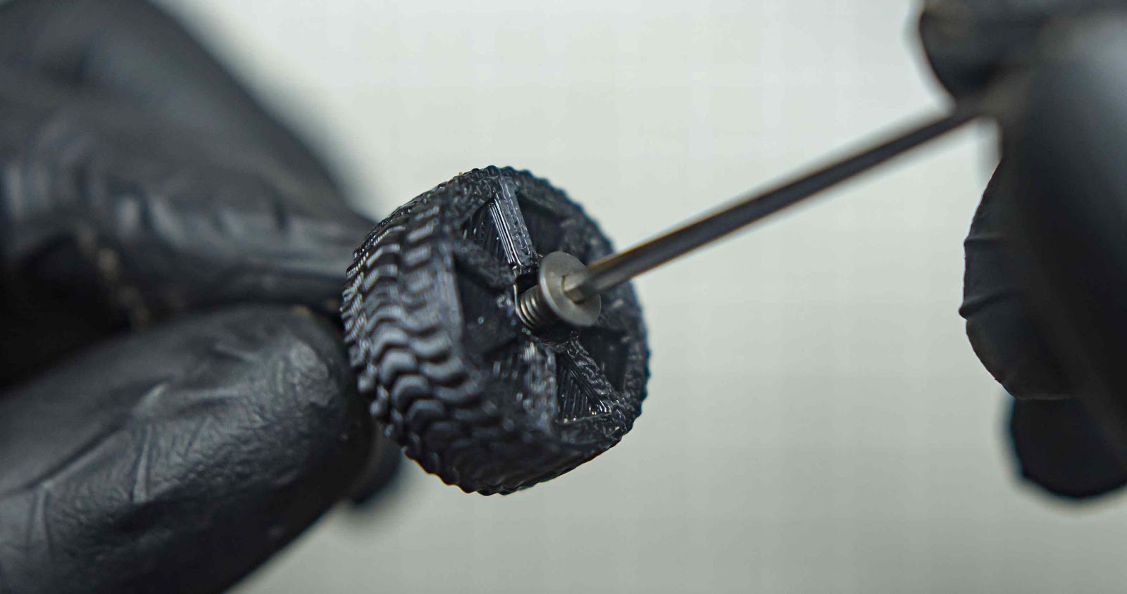
Screw all four wheels into the front and back axials using m3 screws. if your wheels need to be rotated don't tighten the screw that much. if you need to lock the wheels just tighten the screws
Step 5.16
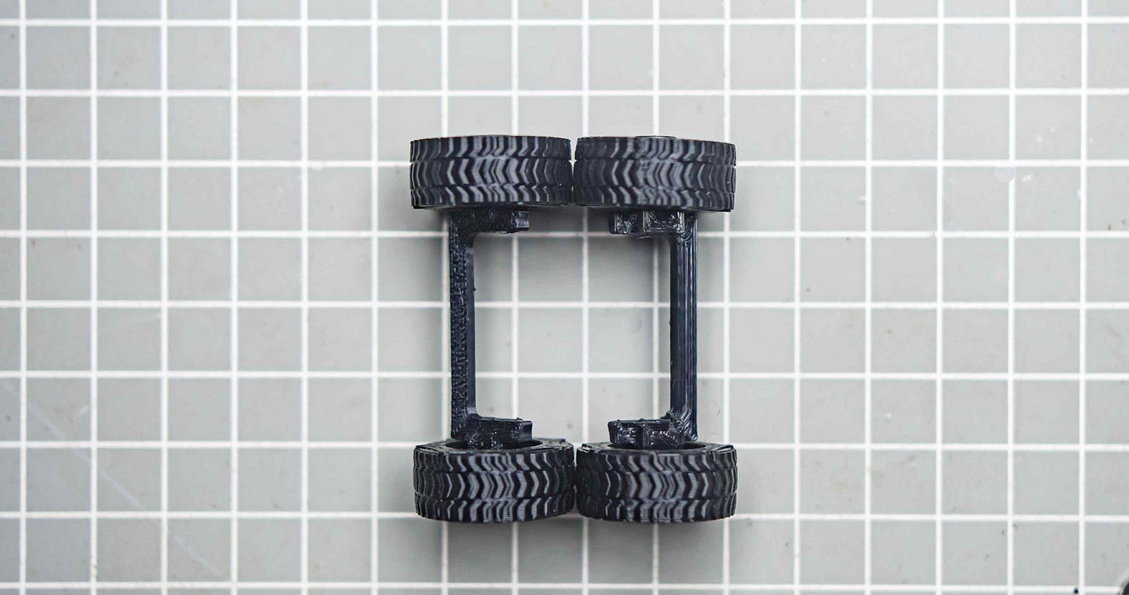
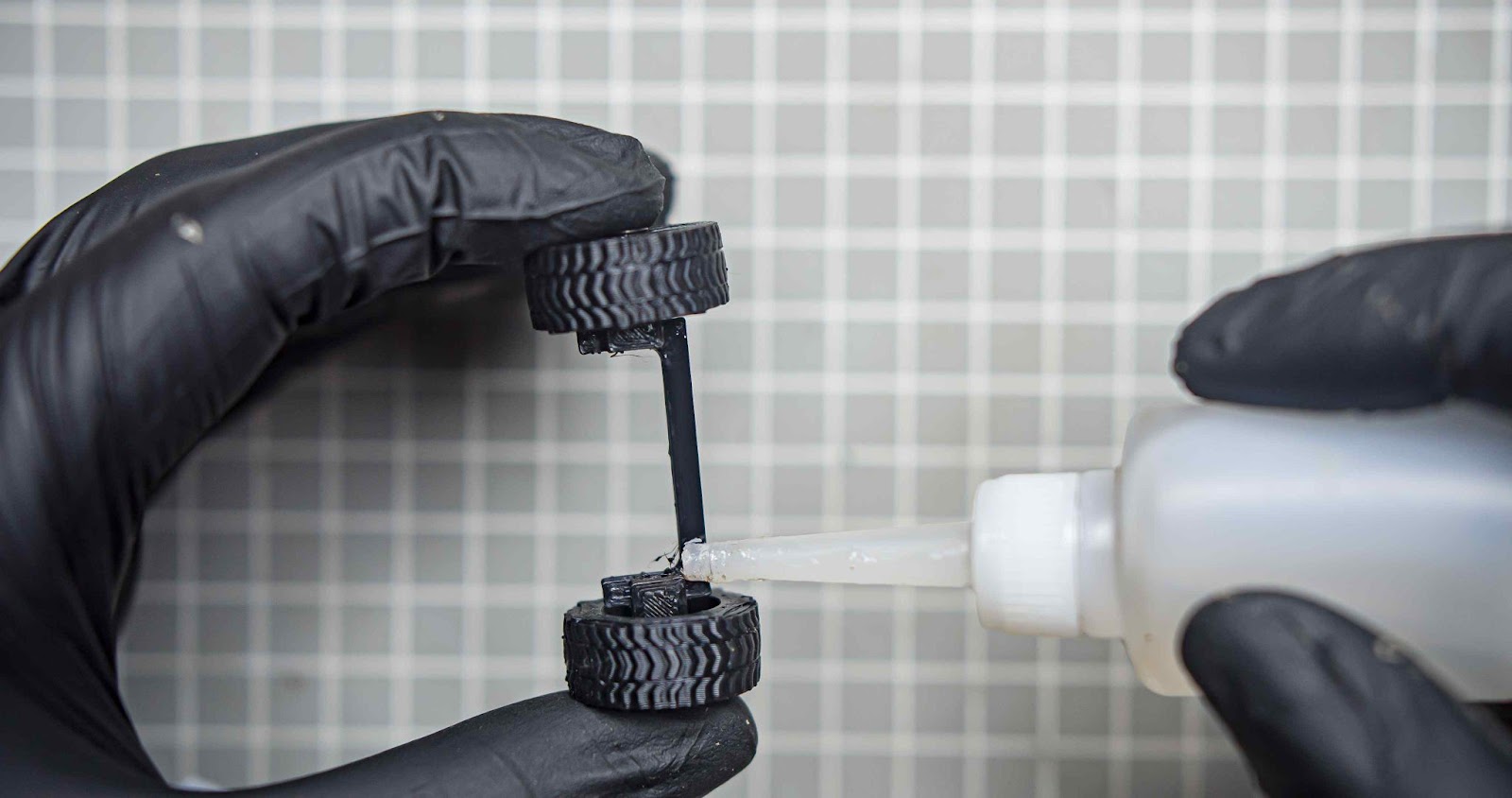
Next using some super glue we will glue the front and back axial under the underframe
Step 5.17
This will be the last step of the build, gluing two rooftop components, on top of the main body
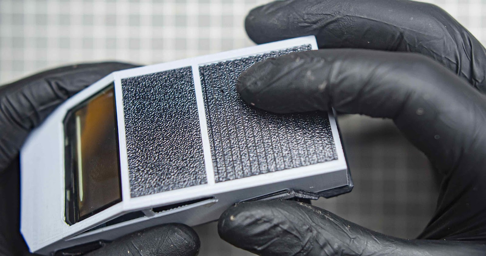
Yes the assembly of the project is completed
Now power on the clock using the slide switch on the back. you can also recharge the battery through Xiao USB
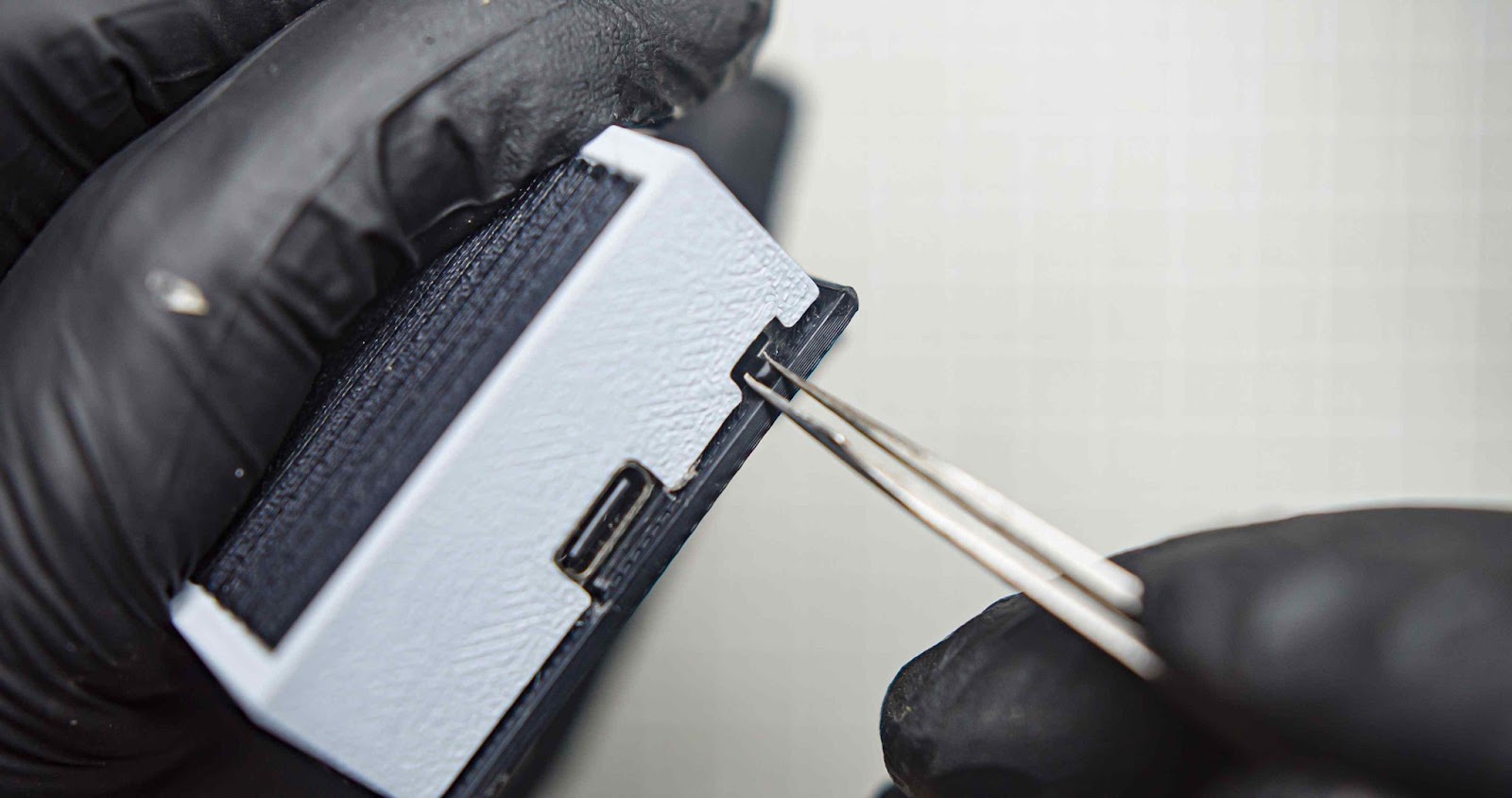
Wait for a few seconds. It will power on. The time will update automatically. if not check your entered wifi password and ssid is correct

Step 6: Troubleshooting
The wheels are not spinning freely: check if the wheel screws are not too tight. also, the hole of the wheels needs to bit larger than the screw. Try to clear the wheel holes after the 3d printing
Time is not updating: During boot-up, the system may initially display the incorrect time, such as the year 1971, but it quickly updates to the correct time. If it not working it will be a network issue also check the Wi-Fi password and SSID you entered during the programming
Battery not charging: the battery can be only charged during the power switch is on. the battery managed through the BMS inside the Xiao
Random sensor data: if the battery is below 20% the sensor might not give data due to low voltage so recharge your battery
Step 7: Final Thought
I believe this project is perfect for car enthusiasts. You can easily build and gift it to friends and family who love cars. It's a great addition to any desk setup, offering a fantastic viewing angle from dusk. This project is truly unique and I think something similar is not available on the market. If you need suggestions for other car models, let me know. There's a lot of potential in this project. We can enhance the software by displaying YouTube subscriber counts, reminders, and Bitcoin value... etc If you're interested in creating more pages for this project, just let me know. I've created a small canvas for you, and now your imagination is the only limit.
thanks
Gokux

Runner Up in the
Making Time Contest


![Tim's Mechanical Spider Leg [LU9685-20CU]](https://content.instructables.com/FFB/5R4I/LVKZ6G6R/FFB5R4ILVKZ6G6R.png?auto=webp&crop=1.2%3A1&frame=1&width=306)


