

Introduction: DC Motor Open Loop Vs Closed Loop Demonstrator


This is a hands-on demonstration of DC Motor Open Loop vs Closed Loop control. Students can simply touch the tires (or use a pencil etc.) and feel the difference between them. There are two very low power motors/tires. One has Open Loop control, and is not as strong. The other has Closed Loop control and increases the voltage when you interfere to try and keep the speed constant. Both can be stopped easily if you grab hard enough, but you can feel the difference.
There is a simple explanation accompanying the demonstration to cover the concept quickly and refer the students out for more in-depth info (see below). I avoided the more advanced concepts of PWM and PID for this level (a FIRST FRC club).
The overall cost is very low since it does not use any industrial motor controllers - just an Arduino to do the Closed Loop corrections.
Supplies


- Arduino Nano - An Uno is fine too - they have the same specs.
- Arduino Nano Terminal Shield - not necessary, but makes connections a bit easier. An Uno with Dupont jumpers would be fine also.
- L298N Dual H Bridge Motor Driver
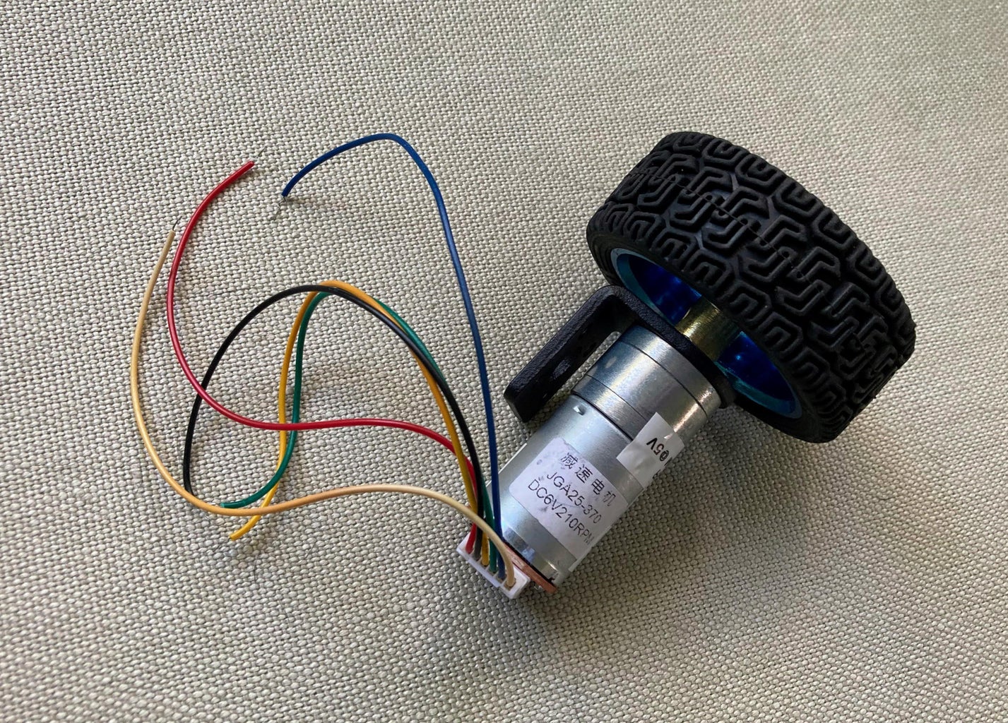
- Motors with Wheels - some keywords are "DC 6V DIY Encoder Gear Motor with Mounting Bracket 65mm Wheel". The ones I used were listed at 120 RPM, but a similar one would be fine.
- Wires, zip ties and mounts etc. and a 12V battery
Step 1: Assembling the Motor and Mounting


I had some 1x scrap pine that I used, and it is ~9.5" x 6" - must have been from a 1x10, but you could also use a 1x6 board and cut off ~9" of it. I made it a bit long with the idea that the battery could sit there. I fastened the brackets to the edges of the board so the wheels would hang off the side and not touch the table it is on. Once the brackets are attached, the motors can be added. The Arduino terminal shield and L298N driver were just screwed to the board with a couple M2 x 8mm (10mm is fine too) washer head self tapping screws (not too tight). Those are the same ones that come with standard servos.
Step 2: Wiring


The motors come with encoders, and a connector with wires pig-tailed. For mine, the colors are:
- Red: Motor -
- Black: Encoder Gnd
- Yellow: Encoder A
- Green: Encoder B
- Blue Encoder +5V
- White: Motor +
The motor polarity is not important - if they spin the wrong way, just reverse the connections.
The encoders are quadrature encoders, so they have an A wire and a B wire. For this demo, though, I just used one of the wires since the direction is always the same.
There are many great tutorials on using the L298N module. For my setup, I removed the ENA and ENB jumpers since this is for a DC motor, and I used the Arduino PWM output on those to drive the motors at different speeds. The IN1-IN4 lines set the H Bridge connections and are connected to Arduino IO pins with digital out commands to move the motors "forward". Switching the high and low on those pairs is another way to reverse a motor. You could just tie them to +5V and Ground too, but since I have a terminal shield, using the Arduino IO is easy.
I kept the voltage regulator jumper on. I am driving the L298N with a 12V battery since that moves the motors a bit faster (there is a 2V drop in the controller, so it's only 10V on the motors, and I am running them at half speed to accentuate the Closed Loop effect). The 12V and Gnd are connected to a 12V battery, and the 5V and Gnd are connected to the Arduino to power it. The L298N Gnd terminal is not very big - I was able to barely fit the wires, and a ferrule or terminal block might help.
The Closed Loop motor (red & white wires) is connected to the OUT1 and OUT2 terminals on the L298N. The Open Loop motor is connected to the OUT3 and OUT4 terminals.
I used 2 female servo wires for the 6 IO pins on the L298N, but Dupont jumpers would be fine too. They are connected like this:
int pin_ENA = 10; // PWM pin for motor 1 - must be an Arduino PWM capable pin
int pin_IN1 = 9; // direction for motor 1
int pin_IN2 = 8; // direction for motor 1
int pin_IN3 = 7; // direction for motor 2
int pin_IN4 = 6; // direction for motor 2
int pin_ENB = 5; // PWM pin for motor 2 - must be an Arduino PWM capable pin
The main thing is that the ENA and ENB pins need to on PWM pins (3,5,6,9,10,11 on the Nano).
Motor 2 is open loop, so you do not need any of the encoder wires.
For Motor 1, I connected the encoder +5V and Gnd to the Arduino, and one of the encoder outputs to pin 2.
Step 3: Coding
I am sure there are improvements that could be made to this code. There are many examples available for the L298N and Arduino.
I used an interrupt routine to count the pulses, and the millisecond timer to set the intervals between corrections to avoid the blocking you get with the delay function.
To get the cpr and rpm_max constants for your motor, make sure to enable the debug print statements.
For the cpr, comment out the motor 1 analogWrite command (in loop) and the "counter1=0" line. Then, turn the wheel by hand for one rotation. The print statements will show you the clicks.
Once you have the cpr set, you can get the rpm_max by re-enabling the "counter1=0" line in loop and add an analogWrite to set motor 1 to full speed in setup.
analogWrite(pin_ENA, 255); // in setup
This is the final code that worked for me:
// 120 RPM motor with 65mm wheel kit open and closed loop demo - two motor/wheel combos
// 2022 Carl F. Sutter
// L298N motor control boards
// 300 RPM at 12V (2V drop on the controller IC), 120 RPM at 5V

#define debug false  // for print statements

int INT_PIN_MOTOR1 = 2;      // INT 0 for motor 1 - is on D2
//int INT_PIN_MOTOR2 = 3;      // INT 1 for motor 2 - is on D3
volatile unsigned int counter1 = 0;   // pulse count for motor 1

unsigned long ul_PreviousMillis = 0UL;  // using millis rollver code from http://playground.arduino.cc/Code/TimingRollover
unsigned long ul_Interval = 50UL;       // 50ms this is delay between corrections - non blocking to allow interrupts to count encoder pulses

// motor control pins in order of the L298N control boards
int pin_ENA = 10; // PWM pin for motor 1 - must be an Arduino PWM capable pin
int pin_IN1 = 9;  // direction for motor 1
int pin_IN2 = 8;  // direction for motor 1
int pin_IN3 = 7;  // direction for motor 2
int pin_IN4 = 6;  // direction for motor 2
int pin_ENB = 5;  // PWM pin for motor 2 - must be an Arduino PWM capable pin

// pwm for each motor - using Arduino PWM, so 0-255
int pwm_max = 255;            // (pwm is 0-255)
int cur_pwm1 = pwm_max / 2;   // the speed we will run at - half speed (pwm is 0-255)
int cur_pwm2 = pwm_max / 2;   // the speed we will run at - half speed (pwm is 0-255)
int cpr = 240;                // the click per rev for the encoder
int rpm_max = 300;            // the 12V open loop RPM
int rpm_target = rpm_max / 2;


// motor 1 pulse count interrupt routine
void ISR_count1() {
  counter1++;
} // ISR_count1


// setup
void setup() {
  if (debug) Serial.begin(115200);


  // set the H Bridge direction for motor 1
  digitalWrite(pin_IN1, HIGH);
  digitalWrite(pin_IN2, LOW);
  // set the H Bridge direction for motor 2
  digitalWrite(pin_IN3, LOW);
  digitalWrite(pin_IN4, HIGH);


  // interrupt routine to count the pulses on the closed loop motor 1
  attachInterrupt(digitalPinToInterrupt(INT_PIN_MOTOR1), ISR_count1, RISING);


  // run the seond motor open loop
  analogWrite(pin_ENB, cur_pwm2);
} // setup


// loop
void loop() {
  unsigned long ul_CurrentMillis = millis();
  if (ul_CurrentMillis - ul_PreviousMillis > ul_Interval) {
    // the count can be used to find the counts per revolution
    if (debug) Serial.print("Count: ");
    //Serial.println(counter1);

    // these lines will show rpm, but zero the counter
    //Serial.print((float)ul_Interval/1000.0);
    int rpm = ((float)counter1/((float)cpr * ((float)ul_Interval/1000.0))) * 60.0;
    if (debug) Serial.print(counter1);
    if (debug) Serial.print(", RPM: ");
    if (debug) Serial.print(rpm);
    // kind of a messy P only correction
    // use the error * half the pwn range
    float error = ((float)rpm_target - (float)rpm);
    float correction = ((error / (float)rpm_max) / 2.0) * (float)pwm_max;
    cur_pwm1 = min(255, max(0, cur_pwm1 + correction));
    if (debug) Serial.print(", PWM: ");
    if (debug) Serial.println(cur_pwm1);
    analogWrite(pin_ENA, cur_pwm1);


    counter1 = 0;  // reset the counter for the next loop
    ul_PreviousMillis = millis();  // reset the timer for the next correction
  }
} // loop
Step 4: The Description
This is the accompanying description:
Open Loop vs Closed Loop Motor Control Demonstration
Touch each wheel to feel the difference. They are both being run at half speed. One has Open Loop Control, and is not as strong The other has Closed Loop control and increases the voltage when you interfere to try and keep the speed constant.
At full speed, we can just run the motors with maximum voltage and do not need any control.
But, we usually want to run at lower speeds so we can turn slowly, or drive slowly up to the target location. Also, two of the same motors rarely run at exactly the same speed, so we need to send different speed commands to each motor to have the robot drive straight.
With Open Loop control, we can simply lower voltage to make the motor spin slower, but that results in less power, so the motors will drive slower on hills and turns.
To solve this problem, we use Closed Loop motor control. We add Encoders to the motor - they report how far the wheel has turned so we can calculate the speed in Rotations per Minute, or RPM.
A Closed Loop control system will monitor the RPM, and increase the motor voltage if it is running slower than desired, and vice versa.
This example is for Velocity Control, and you can also use Encoders and Closed Loop control for Position Control - having a motor rotate to a specific heading, stop, and hold there.
The most common Closed Loop control algorithm is called PID (Proportional, Integral, Derivative). There are tons of great YouTube videos on how PID control works.


