

Introduction: DIY BICYCLE USB CHARGER "Fahrradlader V3.1"


Hi,
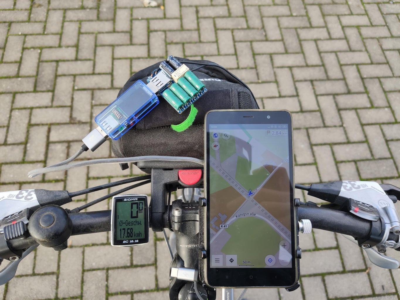
in this Instructable, I want to show you how to build a powerful and intelligent USB-Charger for your bicycle hub dynamo. With this charger you can simplify long distance traveling with your bicycle, because you are not depending on external power solutions like solar chargers or AC-Adapters. You can run your navigation on your smartphone at full brightness while traveling and your battery will always stay at 100%.
But first the story about the charger:
My journey with USB-Chargers started in 2017, where I have published my first charger design here on Instructables. With the design from 2017 the so called " 10€ BICYCLE USB CHARGER ", I have started a lot of tours and it worked okay... But not perfectly, the amount of power was not enough for me. I wanted to get more power out of my dynamo and wanted to build this charger more stable and safe.
Also the charger from 2017 had an over-voltage protection, where the over voltage was burnt in heat, and after the charger is getting over 45°C, it will shut down. This feature was necessary in the design, but for me it was always something I had to optimize...
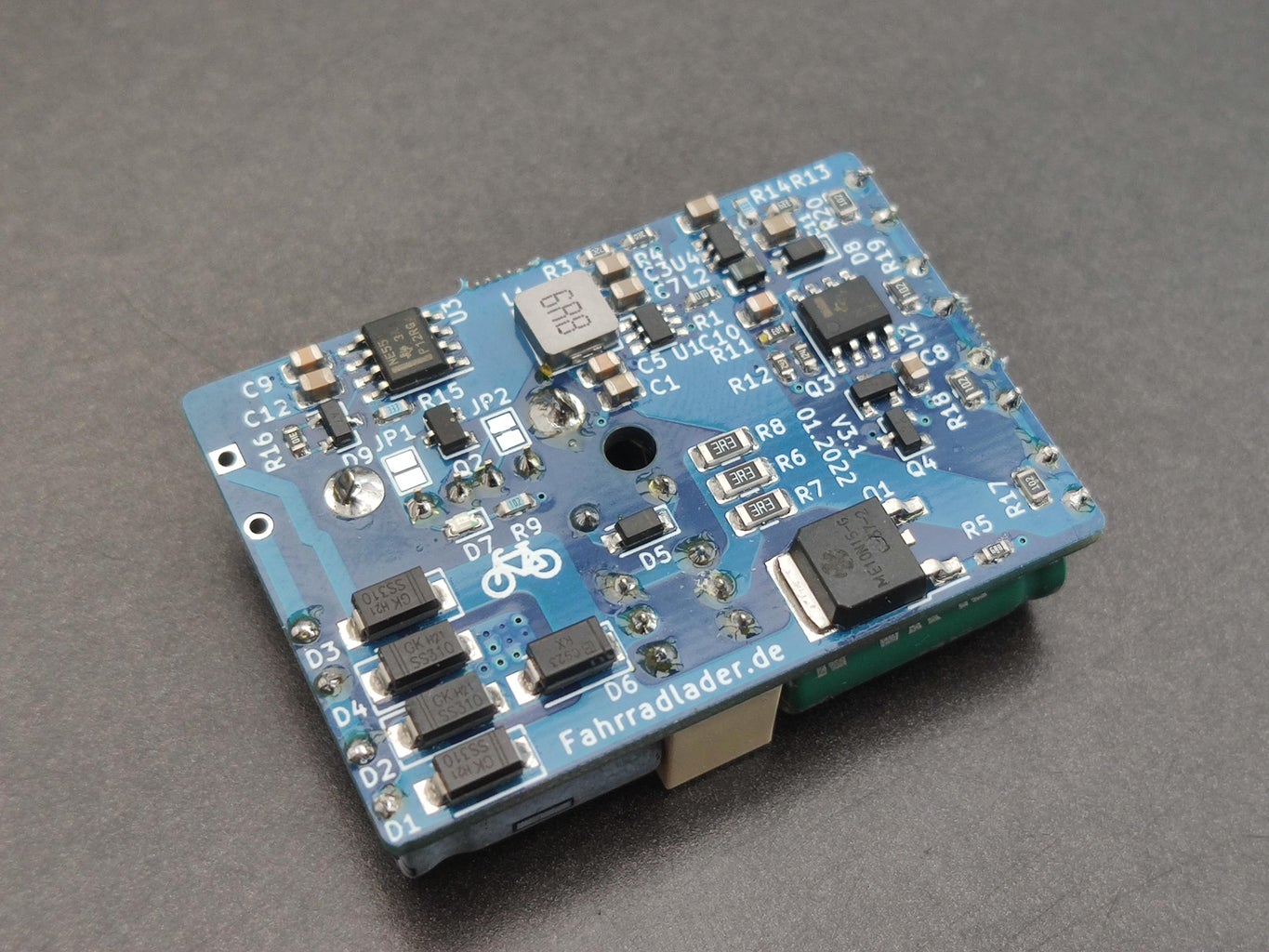
So I started to design a new charger. The Version V3.1 the so called "Fahrradlader V3.1"(German for Bicycle-Charger V3.1)
The specs of the "Fahrradlader V3.1" are:
- Input-Voltage from USB-Hub-Dynamo: 6-100V AC
- Dimensions: 42x33x14mm (LxWxH)
- Supercapacitors: The charger can charge your phone up to 20sec, after you stopped riding
- Capacitive Compensation: For more power at low speeds
- Output Power: 1 Ampere / 5 Volt at 18-20km/h (depends on your Hub-Dynamo)
- Charge-Optimizer: Charge your phone always with the maximum of the aviable power
- No heat due Overvoltage. The charger stays cool and can even charge at 100km/h
- Cost:+-20€ (Material)
I decided to make the charger Opensource, so you can build the charger
by yourself. If you don't have the opportunities to build the charger at home, because you have no soldering tools for SMDs, you can also find pre-assembled and tested chargers on my new Website, there you will also find some more information: Fahrradlader.de (German only)

### If you like my Instructable, please vote for me in the Anything Goes Contest ###
Follow me on Instagram: @vulcaman
Step 1: Functionality


The bicycle charger V3.1 is built on the basis of four 3F supercapacitors. These are first connected to the dynamo with a relay. When you start your ride, the supercapacitors are charged by the dynamo. If the voltage at the supercapacitors reaches a value of ~5V, the bicycle charger is active and passes on its 5V voltage to the USB port. In addition, the relay is opened at this point and the charging is now continued via a 150V power MOSFET. This is done because the installed relay only has a lifetime of about 100 million switching operations. The installed MOSFET, on the other hand, has far more switching operations and also switches electrically and not mechanically.
After the relay is switched off and the MOSFET is switched on, the super capacitors continue to charge up to a voltage of 10V. Once this voltage is reached, the MOSFET opens and disconnects the bike charger from the dynamo. Now the advantage of the supercapacitors comes into play. Due to the extremely high capacity, the charging process can now be completely pre-set from the supercapacitors. In the process, the voltage at the supercapacitor slowly drops. When the volatage reaches a value of ~8V, the MOSFET closes again and the capacitors charge back up to their 10V.
The advantage here is that the charger is completely disconnected from the dynamo. No overvoltage etc. is dissipated in heat. Also an interruption of the charging process at very high speeds is thereby excluded!
Another advantage of this is that the charging process can be continued even at a standstill. Thus, the charging process can be continued for several seconds depending on the charging current.
Until the charging process begins, it takes about 10-15sec from the start of driving.
Step 2: Performance Optimizations


USB-CHARGE-OPTIMIZER
Through experimental testing of various smartphones (Xiaomi Mi9, Redmi Note 3 Pro as well as a Huawei tablet), I noticed that the charging current is always set at the beginning of the charging process. This is advantageous for a normal charger for the wall socket, since the maximum current is drawn that way. Unfortunately, this is different with the bicycle charger... . Here is not directly at the beginning of the maximum power, because when the charger at ~10km / h begins to supply power, the charger can not yet provide the maximum power. Only at 18km/h the ~700mA-1A are provided. And here's the problem: The smartphone initially sees at 10km/h that it can only draw ~100mA and sets this value for the entire charging process, even if the charger can deliver 700mA-1A at 18km/h or more!
To prevent this problem, I have installed a switch (MOSFET), which restarts the charging process approximately every 15sec, so that the smartphone can always draw the maximum available power. If this function is not desired, it can be suppressed by connecting jumper JP1 with a blob of solder.
USB Dedicated Charging Port
If you just connect 5V to the USB port without looking at the D+ and D- data ports, the smartphone will not see the charger as a possible charger and will limit the charging current to 500 mA max. However, if you short D+ and D-, the smartphone recognizes the charger as a DCP (Dedicated Charging Port) and the smartphone (depending on the model) now knows that it can draw up to 1.8 amps. The Fahrradlader V3.1 is recognized by all popular smartphones as DCP.
Step 3: Source-Files and BOM
Below you will find the complete schematic of the charger. This charger is open-source, so everyone who wants to rebuild the charger can build it from this schematic:

BOM:
| Quantity | Description | Link |
|---|---|---|
| 1x | 6,8 Ohm 0603 Resistor | - |
| 1x | 1k 0603 Resistor | - |
| 1x | 10k 0603 Resistor | - |
| 1x | 10,5k 0603 Resistor | - |
| 1x | 24k 0603 Resistor | - |
| 1x | 30k 0603 Resistor | - |
| 1x | 33k 0603 Resistor | - |
| 2x | 54,9k 0603 Resistor | - |
| 1x | 100k 0603 Resistor | - |
| 1x | 120k 0603 Resistor | - |
| 1x | 1M 0603 Resistor | - |
| 4x | 1k 0805 Resistor | - |
| 3x | 3,3 Ohm 1206 Resistor | - |
| 3x | 100nF 0805 100V Capacitor | - |
| 1x | 1uF 0805 25V Capacitor | - |
| 1x | 10uF 0805 25V Capacitor | - |
| 5x | 22uF 0805 25V Capacitor | - |
| 2x | 470uF 8x16mm Polarized Capacitor LOW-ESR | - |
| 4x | 3F Super-Capacitor 2,7V LOW-ESR 8x20mm | - |
| 4x | SS310 SMA Schottky Diode | |
| 2x | SD103AW Schottkydiode SOD-123 | |
| 1x | BAV99 Diode SOT-23 | |
| 1x | MMBT2222A NPN SOT-23 Transistor | Aliexpress |
| 1x | MMBT3906 PNP SOT-23 Transistor | |
| 1x | AO3401 SOT23 P-Channel Mosfet | |
| 1x | ME10N15 150V TO-252 N-Channel Power MOSFET | - |
| 1x | 0603 LED Green | |
| 1x | 6.8uH Power Inductor | - |
| 1x | MT3608 Boost Converter | |
| 1x | ZTP7193T Buck Converter 3A | - |
| 1x | LM358 SOIC-8 OPAMP | |
| 1x | NE555 SOIC-8 Timer IC | |
| 1x | Omron G6S-2 5V | |
| 1x | USB-A Connector |
Attachments

Step 4: More Theory :-)
In this step I want to show you some more Basics, for an better understanding, how the Capacitive Compensation in the charger works. With this knowledge you can improve the output power of a dynamo charger significantly
Rectifier

The rectifier is the component in the bicycle charger which generates a DC voltage at the capacitor from the AC voltage of the dynamo, the so-called DC link capacitor. If the DC link capacitor is sufficiently large, the voltage can be assumed to be constant. The voltage at the DC link capacitor is equal to the peak voltage of the alternating voltage of the dynamo minus the diode voltage.
Diode-Losses

This diode voltage is the first challenge in the construction of a bicycle charger. Because the power output from the dynamo is limited. According to the data sheet, most dynamos deliver 3W power at 6V nominal voltage. With this low power you should keep house, because the goal is to bring most of the power to the USB device.
Critical for the rectifier are the conduction losses at the diodes. According to Ohm's law, these are made up of the product between the current and the forward voltage of the diode. For this reason, Schottky diodes are installed in every bicycle charger as rectifiers, which have low forward voltages. Here I have used SS310 SMA Schottky Diodes
Capacitive compensation

The capacitive compensation is one of the main point in the bicycle charger, with which the power output of the dynamo can be increased. The compensation tries to compensate the internal inductance of the dynamo with an corresponding capacitor. In the complex alternating current calculation, the reactance of the inductance increases linearly with the frequency. For the capacitor, a -1/f behavior applies. If the inductance and the capacitor are tuned to each other, resonance occurs at the resonant frequency. At this frequency, the reactance of the inductance is equal to the reactance of the capacitance, but with the opposite sign. Since the inductance and the capacitor are connected in series, the total resistance is the sum of both. This results in a total reactive resistance of 0 Ohm at resonant frequency.
The disadvantage of compensation is that it only occurs at one frequency. In practice, this means that the resonance frequency in the bicycle loader only occurs at exactly one driving speed. From experimental studies, a capacitance of ~220uF as a series capacitor has been found to be ideal for a normal driving speed.
However, such high capacitances are difficult to obtain as a bipolar component. Most capacitors in this size are electrolytic capacitors and consequently unipolar. However, two electrolytic capacitors can be connected in opposite directions, resulting in a total unipolar capacitance. To obtain the ~220uF as series capacitance, two 470uF capacitors must now be used in series. It is important to choose a LOW-ESR type of capacitor to reduce the losses at the capacitor.
Step 5: Characterization of the "Fahrradlader V3.1"


In order to test the function of the Fahrradlader V3.1, I have built a laboratory setup that allows me to run it at a variety of operating points. To do this, I clamped a Shimano DH-3N30 in my lathe to test the Fahrradlader V3.1 even under extreme conditions such as a speed of 100km / h.
Measurement points & connection
 For the measurement at the bicycle charger, I have chosen a total of four measuring points: On channel 1 the gate voltage of the power MOSFET is measured. On channel 2 the voltage at the supercapacitors is measured. On channel 3 the input voltage at the rectifier and on channel 4 the 5V voltage at the output of the charger. The following test is performed at a speed of ~ 30km/h and with a load of 500mA at 5V.
Measurement results
The following measurements illustrate the operation of the Fahrradlader V3.1 . In addition, the measurement results demonstrate how important the overvoltage protection on the dynamo is. Already at less than 30km/h voltages spikes of over 100V occur at the dynamo in idle.

This measurement shows the start of a charging process at the supercapacitor. If the voltage at the capacitor drops to <8.12V (CH2), the MOSFET switches on (CH1) and the charging process begins. Before charging, however, clear voltage peaks with amplitudes >100V(CH3) can be seen at the rectifier input . Higher peaks can not occur, because they are limited by a 100V TVS diode. The output voltage (CH4) remains constant at 5V.

This measurement shows the charging behavior of the supercapacitor over a longer period of ~14s. You can see how the supercapacitor charges to 10.12V and discharges to 8.12V. The voltage of 5V at the output is permanently present and a load of 500mA is connected to the bicycle charger.
Step 6: Soldering of the Chargers


I have soldered all the PCBs by myself in my DIY Reflow-Oven .
The PCB has on the one side only SMD-Components and on the other side only THT-Components. So it is very easy for me to solder just one side SMD in the oven and then manually solder the THT-Components from the other side.
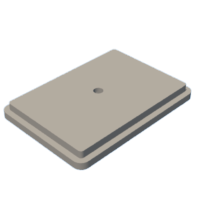
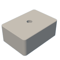
Step 7: 3D-Printed Case
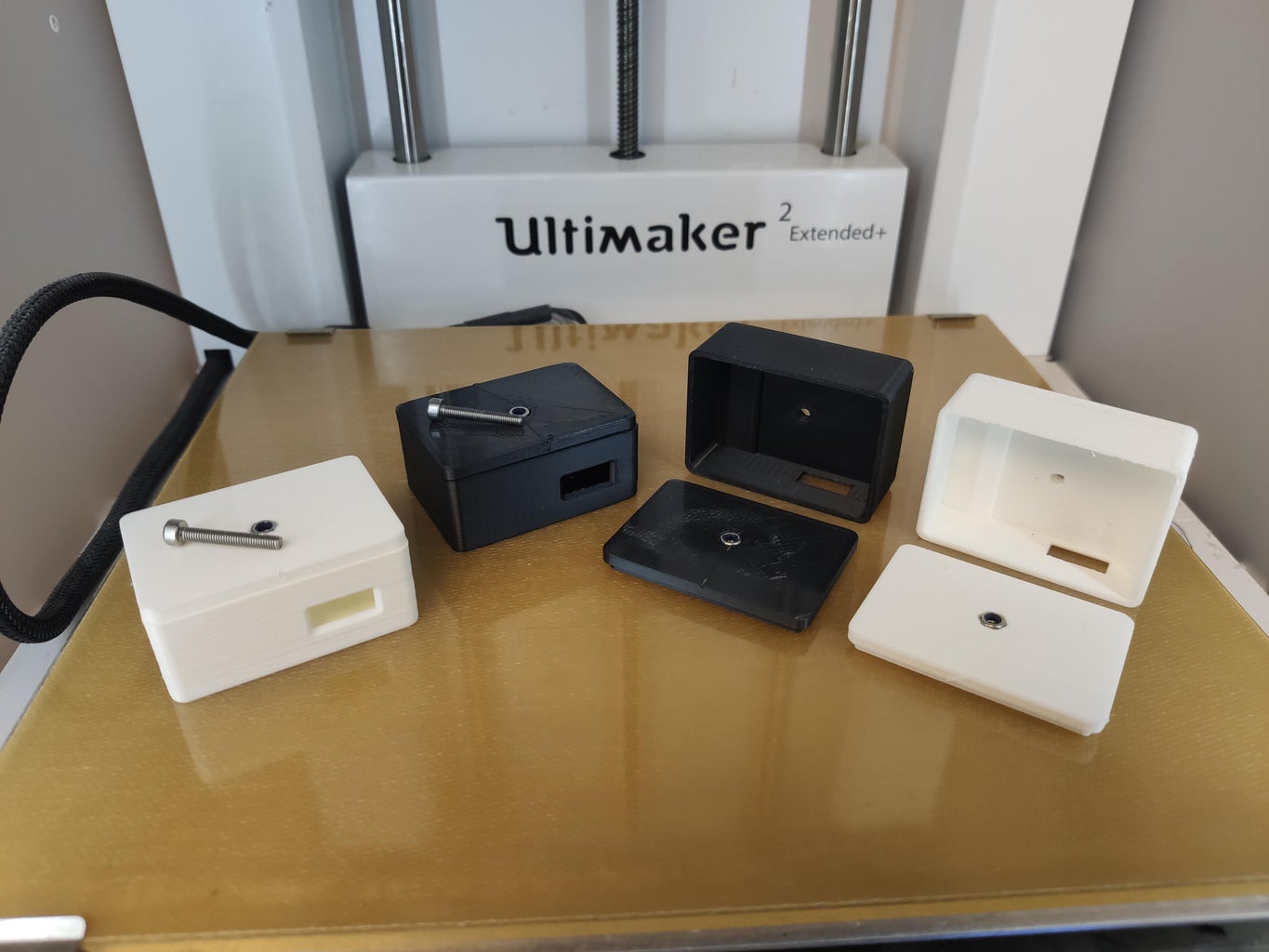


The USB-Charger is installed inside the front bag of my bicycle. But the charger is not alone inside the bag, so I designed a small case for the charger, for a better handeling :-)
Below you will find the .stl Files for 3D-printing
Step 8: Connection to Your Bicycle


To connect the Charger to your bicycle hub-dynamo, you just need to connect the AC-Connection from the charger to the AC Connection of the hub-dynamo and the ground to the ground connection. And thats it :-)
Step 9: Testing the Bicycle Charger


To test the charger I recommend to use a USB-Doktor. These tiny devices can log the current, the charging time and the mAh. As you can see, I have done a little test ride by 10 minutes. In that time, I have charged my phone with 253mAh Capacity, which is really good! Remember my Smartphone has a battery of 4000mAh capacity.
You can find a USB-Doktor here: Aliexpress
Step 10: Troubleshooting and Support
With this instructable, I wanted to create a real benefit to all people, who done long distance traveling with their bicycle and don't have a power plug by hand. With this charger you can be completly indepented from additional power sources.
If you build the charger please feel free to contact me, if you have any questions :-)

Participated in the
Anything Goes Contest 2021


