Introduction: DIY Solar Bottle Lamp V2.0


Plastic accounts for 85% of marine litter and warns that by 2040, volumes of plastic pollution flowing into marine areas will nearly triple, adding 23-37 million metric tons of plastic waste into the ocean per year. This means about 50kg of plastic per meter of coastline worldwide.
The consequences of the above problem are:
1. Plastic pollution threatens food safety and quality, human health, and coastal tourism, and contributes to climate change.
2. Marine species ingest or are entangled in plastic debris, which causes severe injuries and death.
The main goal of this project is to reuse the tons of plastic bottles that are thrown into the garbage.
The core concept of the DIY Solar Bottle Lamp has two missions:
1. To prevent waste by repurposing and upcycling water and soft drink plastic bottles that are discarded and further contaminate the planet.
2. To make free solar-powered lights available to everyone.
A few months ago I have published an Instructables on Solar bottle Lamp, which was highly appreciated by the people. If you don't know what is solar bottle lamp? let me introduce you, Solar Bottle Lamp is a solar-powered light that is constructed from waste plastic bottles. The design idea is to reuse waste plastic bottles by attaching a 3D-printed solar lamp in place of their old plastic cap.
Solar Bottle Lamp was featured on the Cover page of Make Magazine Vol-82.
My Book : DIY Off-Grid Solar Power for Everyone
You can order my Book on Off-Grid Solar Power from Amazon
Support me On Patreon:
If you enjoy my work here on Instructables, consider joining my Patreon, it will be a great help for me to make more interesting projects in the future.
Patreon Link: https://www.patreon.com/opengreenenergy
Supplies

QUANTITY COMPONENT NAME
You can buy the fully assembled kit from our Tindie Store
1×Charger IC - LP4060B5F ( Aliexpress / LCSC )
1×Battery Protection IC - AP6685 ( LCSC )
1×Transistor - MMBT3904 ( Amazon / Aliexpress )
1×MOSFET - AO3400A ( Amazon / Aliexpress )
1×SMD LED - 0.5W ( 2835 ) ( LCSC )
1×Blue SMD LED ( 0805 ) ( Amazon / Aliexpress )
1×1/8W SMD Resistors - 1K, 10K ( 0805 ) ( Amazon / Aliexpress )
1×1/4W SMD Resistors - 6.8R,12R, and 27R (1206 ) ( Amazon / Aliexpress )
1×SMD Capacitors - 100nF, 1uF, 10uF ( 0805 ) ( Amazon / Aliexpress )
1×Schottky Diode SS14 ( Amazon / LCSC )
3×JST Connectors ( Amazon / Aliexpress / Amazon )
1×Flashlight Button Switch
1×USB - C socket
1×Solar panel - 60 x 60 mm/ 5.5V ( Tindie / PCBWay )
1×18650 Li-Ion Battery
1 x PCB Set ( Main PCB + LED PCB ) ( PCBWay )
You can order the fully assembled PCB Set from PCBWay
Step 1: How the Solar Lamp Works

The solar panel receives sunlight from the sun and converts it into electrical energy. The controller board charges the battery during the daytime and drives the LED during the nighttime.
The solar lamp can be considered as a standalone Solar Photo Voltaic (SPV) system and contains four basic components:
1. Solar Panel: Convert Solar Energy to Electrical Energy
2. Controller: Charge the Battery ( Charger ) and drive the Load ( Driver )
3. Battery: Store the Electrical Energy
4. Load (LED): Provide the desired light output
Step 2: How the Circuit Works?

The entire circuit is broadly dived into 3 parts:
1. Charger Circuit
2. Battery Protection Circuit
3. LED Driver Circuit
The power generated by the Solar Panel is extracted by the charger circuit and charges the battery. The protection circuit is responsible for providing various protections to the Li-Ion Battery. The LED driver circuit is responsible for driving the LED.
Charger Circuit:
The charger circuit charges the battery by taking power generated from the solar panel. It is based on a lithium-ion battery charger IC LP4060. It is a complete constant-current/constant-voltage linear charger for a single-cell lithium-ion battery. It uses only a few external components like resistors and capacitors. The circuit is based on the application circuit given in the datasheet.
USB Charging: It uses a vertical mount USB-C port with two pull-down resistors R1 and R2. The Schottky diode D1 is used to prevent reverse power flow.
Battery Protection Circuit :
The Battery Protection Circuit provides various protections to the Li-Ion battery. The circuit is based on IC - AP6685 which contains internal power MOSFET, high-accuracy voltage detection circuits, and delay circuits. The IC has the following protections inbuilt:
1. Reverse polarity protection
2. Over Charge Protection
3. Over-Discharge Protection
4. Load short circuit protection
LED Driver Circuit :
The LED driver drives the LED as well as controls the brightness. It also provides automatic turning ON during the night. The circuit works as follows
During the day, the solar cell has voltage to D1-diode to bias transistor Q2 it conducting collector and Emitter closed, so it does not have the voltage to the gate of MOSFET Q1. It is OFF so the LED will go out. At the same time, the current from the solar panel will charge the battery.
When there is no sunlight, no solar current to base Q2, So it will not conduct but at the same time, MOSFET Q1 will conduct. Now the battery’s current will flow to LED through the resistors ( R7, R8, or R9 ).
The button switch is used to connect either R7, R8, or R9 in the LED circuit. When the pole is connected to R7, the brightness is Low, when connected to R8, the brightness is Medium and when connected to R9, the brightness is High ( Low Resistance, High LED Current through the LED)
Step 3: Battery Sizing


Earlier I used a 0.5W straw hat LED, but it is not so efficient and the lumens/watt is around 70-80.
So I am planning to replace the LED with a 0.5 Watt cool white SMD LED ( 2835 package). As per the SMD LED datasheet, the forward voltage (Vf) is 3.2V and the luminance is 150 lumens per watt.
My target lumens for the different modes of operation are as follows:
1. Mode-1 ( Low Brightness ): 15 Lumens with a backup time of 24hrs
2. Mode-2 ( Medium Brightness ): 30 Lumens with a backup time of 10 hrs
3. Mode - 3 ( High Brightness): 70 Lumens with a backup time of 5hrs
The power required to drive for the above modes is as follows:
1. Mode-1: 15/150 = 0.1W
2. Mode-2: 30/150 = 0.2W
3. Mode-3: 70/150 = 0.467W
In the following table, calculations are presented to estimate the battery capacity. I have considered a 18650 Li-Ion battery (3.7V) with 80% DOD.
From the above table, the maximum charge required for the battery is 928.1 mAh. However considering the market availability and taking some additional margin for sunny days, the final battery size selected is 1200 mAh.
Step 4: Selecting the Solar Panel


The calculated Watt-hours required to drive the LED is 2.75 Wh, considering peak sun hour is 4.5 for most places in India, the solar panel size shall be as follows:
Considering the Battery Efficiency 90%, the effective Wh required = 2.75/ 0.9 = 3.05 Wh
Sun Hours = 4.5 Hrs
Solar Panel Wattage = 3.05/4.5 = 0.679 W
So we need a solar panel larger than the above-calculated value ( 0.68 W ). The available area in my enclosure to place the solar panel is 60 x 60 mm2. The suitable voltage for the solar panel to charge the 3.7V battery is 5.5V. There are many 5.5V solar panels available in the market with this standard size, the typical wattage is in the range of 0.4 -0.45W.
Finally, I decided to use Sunpower solar cells to get the maximum possible wattage ( 0.55W) within this limited area. Following are the specifications of the Sunpower Solar panel, that I am going to use in my final product.
Now you can order this solar panel from Tindie Store.
Step 5: PCB Design


I have designed a new PCB as per the schematic V2.0. There are two different PCBs
1. Main Board
2. LED Board
Main PCB Board:
The main PCB includes all the circuits for charging the battery, LED driver, and battery protection. I have used all the SMD components with the 0805 packages ( except the LED current limiting resistors R7, R8, and R9 which are 1206 packages) so that they can easily be hand soldered.
LED PCB Board:
The LED PCB board only uses the 0.5W SMD LED ( 2835 package ).
You can download or buy the above PCB from PCBWay
You can also buy the fully assembled kit from our Tindie Store
Step 6: Solder the SMD Components


It's very important to first clean the PCB with some isopropyl alcohol. Then apply solder paste on the pads by using a solder paste syringe. Place parts with tweezers making sure that LEDs, chips, etc. are properly aligned. I like having a second board with no paste on it to see the alignment dots.
Now you have many options to cook the PCB like a hot air soldering gun, Hot plate, reflow oven, etc. I have used my Miniware MH30 hot plate to solder the PCB. Set the temperature according to your solder paste melting point and place the PCB on the hot plate.
It is important to look at the reflow profiles of all your components, to see how long you can heat your components for, and at what temperature. I usually just "wing it", and heat them at about 250C, for about a minute. You will see the solder melting, and the components being soldered into their respective places. Now you can turn off the hot plate and let it cool down completely.
Step 7: Solder the Through Hole Components

In the PCB there are 3 through-hole components, JST connectors, a push button switch, and a USB-C connector.
First, align the JST connectors as per the Silkscreen on the top side of the PCB then solder them.
Then insert the push button switch and USB-C connector from the bottom side of the PCB as shown in the above picture, then solder them.
Once you have completed the soldering process it is important to remove the flux from PCB. Spray a small quantity of IPA (Isopropyl alcohol) Solution and clean it with cotton.
Now the PCB boards are ready to use.
Step 8: Prepare the Battery Pack


I was planning to use a readymade single-cell 18650 battery pack with a JST connector. However, I didn't find the desired capacity battery pack, so decided to build my own.
First I have attached an insulating gasket ring on the positive terminal of the battery. Here I have used a 1200mAh battery.
Then aligned the nickel strips with the help of Kapton tapes. Then spot welded the nickel strips to the battery terminals.
At last, solder the JST connector to the nickel strips. Be sure you are connecting to the right polarity.
Step 9: Prepare the Solar Panel


The solar panel has two terminals with polarity marked on it.
First tin the terminals apply a small amount of solder on the tip of your soldering iron.
Then solder the JST connector with the correct polarity. You may see the above image for your reference.
Step 10: Prepare the LED

The LED PCB has two solder pads with polarity marked on it.
First tin the terminals apply a small amount of solder on the tip of your soldering iron.
Then solder the JST connector with the correct polarity. You may see the above image for your reference.
Step 11: Testing the PCBs


After assembling the PCBs, we can move to test the entire circuit.
Connect the JST connector for LED, Battery, and Solar panel to the main PCB board.
Then connect a USB-C charger to the PCB for testing the charging circuit. The blue LED on the PCB indicates that the battery is charging. The maximum charging current is 500mA. The LED will be turned off when the battery is fully charged.
Similarly, you can test the solar panel charging circuit, by placing it under direct sunlight. I have just tested the fast-forward method by applying high-brightness light over the solar panel.
After the battery is fully charged, you may unplug the USB charger or cover the solar panel with a dark object ( place it upside down as shown in the above image )
Press the button switch, and you will hear a click and LED will turn on at low brightness mode. Similarly, there are 4 modes of operation ( LOW- MEDIUM-HIGH-OFF ), in each step of a switch, you will operate the lamp in a new mode.
Step 12: 3D Printed Enclosure


https://www.thingiverse.com/thing:5584204
I have used my Creality CR-10 Mini printer and 1.75 mm PTEG filaments to print the parts. I have printed it in 3 different colors yellow, Orange and Cyan. The diffuser is printed in a transparent filament. You need a support structure for printing the main body and top cover.
My settings are:
1. Print Speed: 60 mm/s
2. Layer Height: 0.2mm
3. Fill Density: 25%
4. Extruder Temperature: 235 deg C
5. Bed Temp: 75 deg C
Download the STL files from Thingiverse
Step 13: Install the Solar Panel


You have to use a solar panel that can be fitted to the enclosure. The size of the solar panel that is suitable for the enclosure is 60 x 60 mm.
Earlier, I designed the slot for a readymade solar panel from PCBWay which have terminal pads at the center that's why the enclosure cutout is at the center. But later on, I made a customized solar panel that is specifically designed for this project. The new panel has terminal pads located slightly upward. So, I have drilled two holes to pass the terminal wires from the solar panel.
Note: I have already modified the design file in line with the new solar panel, so you don't need to drill. You can see the modified design file in the above picture.
Mount the solar panel on the top cover by using epoxy glue.
Seal the panel from the inside also, so that water will not enter the enclosure.
Step 14: Install the LED


Insert the JST connector wire into the enclosure slot, then align the PCB to match the screw position.
Apply a small amount of epoxy glue and mount press the PCB hard.
Then secure the PCB farmly by using two screws.
Seal the back side of the LED PCB from the inside also, so that water will not enter the enclosure.
Step 15: Install the Button Switch Cap


The button cap is used to extend the actual switch to the user's approachable position.
Align the button cap as shown in the picture and press it.
To protect the switch from outside dust and water, I have designed a button switch cap. You have to print it on rubber or flexible material.
Step 16: Install the PCB


Align the PCB mounting holes with the mounting studs in the enclosure. Then secure it with two M3 screws.
The best way to align is to match the USB-C into the enclosure slot, the other things will be automatically aligned.
Step 17: Install the Battery


Now mount the 18650 battery pack into the 3D-printed enclosure.
Keep the terminal wires in the upward direction as shown in the above image.
You may apply small glue to fix it, I will recommend to not use superglue, otherwise you will never replace the battery pack.
Step 18: Close the Lid

After installing all the parts, close the top cover by aligning the mounting studs. For a better joint, a snap-and-fit arrangement is also provided on the top cover. Now use M3 screws to tighten both the parts together. You may apply epoxy glue at the joints to make it weatherproof.
Step 19: Install the LED Diffuser

The LED diffuser serves two purposes: diffuse the light coming from LED and protect the LED PCB from water ingress.
Apply a small amount of sealant around the diffuser slot, then press it to fix it properly.
You may also seal it from the outside at the jointing part, to make sure water will not enter into the LED PCB.
Step 20: Install the Bulb Attachment

I have designed a new attachment for the lamp to use as the solar light bulb.
The attachment can be mounted in place of the bottle. It will be very useful for reading or camping.
Step 21: Prepare the Bottle


The solar lamp is compatible with any soft drinks bottle cap. Take an empty soft drinks bottle and clean it thoroughly.
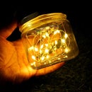
Fill the bottle with water and add a few drops of chlorine to avoid algae formation.
Close the bottle with Solar Bottle Lamp and your lamp is ready.
Step 22: Charge the Bottle Lamp

Before first use, charge the battery by placing the bottle lamps in bright sunlight for at least a day.
You may also charge the lamp by using a USB-C charger ( Max 5V)
Step 23: Use It As Camping Light

The lamp has a hanging arrangement that will be useful for hanging the lamp at any desired place.
You can also hang it on your backpack by using a camping hook so that the lamp will charge when you are on the way.
Step 24: Finishing


Hope my solar light bulb will give light to many rural people around the globe.
If you enjoyed this article, don’t forget to pass it along!
Follow me for more DIY projects and ideas. Thank you !!!