Introduction: DIY Solar Panel Monitoring System – V2.0


Welcome to all renewable energy enthusiasts and electronic hobbyists. Solar power, with its sustainability and vast potential, is an indispensable source of renewable energy. However, to optimally harness this power, we require a tool to monitor and control the performance of solar photovoltaic (PV) systems.
This Instructable intends to provide a detailed, step-by-step guide on constructing a comprehensive solar PV monitoring system. The system integrates a variety of components including the ACS758 sensor, ADS1115 Analog-to-Digital Converter (ADC), Xiao ESP32 microcontroller, and an OLED display. Additionally, to enhance the system's capabilities, we will incorporate a voltage divider for accurate voltage measurement, a DS18B20 temperature sensor to monitor panel temperature, an XL7015 voltage regulator to maintain a steady power supply, and a battery connector for energy storage.
My Book : DIY Off-Grid Solar Power for Everyone
You can order my Book on Off-Grid Solar Power from Amazon
Support me On Patreon:
If you enjoy my work here on Instructables, consider joining my Patreon, it will be a great help for me to make more interesting projects in the future.
Patreon Link: https://www.patreon.com/opengreenenergy
Supplies

Components Used:
1. XIAO ESP32C3 ( Amazon | Aliexpress )
2. ADS1115 Module ( Amazon | Aliexpress )
3. ACS758 Module ( Amazon | Aliexpress )
4. XL7015 Buck Converter ( Amazon | Aliexpress )
5. OLED Display ( Amazon | Aliexpress )
6 .Resistor ( 100K , 10K, 4.7K, 2K , 1K ) ( Amazon | Aliexpress )
7. 0.1 uF Capacitor ( Amazon | Aliexpress )
8. Screw Terminal 2P – 9.52mm ( LCSC )
9. Screw Terminal 3P- 3.5mm ( LCSC )
10 PCB Board ( PCBWay )
Tools Used:
1. 1Soldering Iron ( Amazon )
2. Nipper ( Amazon )
3. Wire Stripper ( Amazon )
4. 3D Printer ( Amazon )
Step 1: The Core Components

ACS758 Current Sensor
The ACS758, a Hall Effect-based linear current sensor, provides an analog voltage output proportional to the sensed current. It's a robust, high-accuracy component that can measure both AC and DC currents, making it perfect for monitoring the power flow in a solar PV system.
ADS1115 ADC
The ADS1115 is a precision, 16-bit Analog to Digital Converter (ADC) that is used to convert the analog voltage signal from the ACS758 into a digital format that can be processed by the Xiao ESP32.
Voltage Divider
A voltage divider circuit will be used to step down the high voltage output from the solar panel to a level that can be safely measured by the ADS1115. It does so by dividing the input voltage into a smaller, proportional voltage using two resistors.
DS18B20 Temperature Sensor
The DS18B20 is a digital temperature sensor that provides high-precision readings over a wide temperature range. Monitoring temperature is essential as the efficiency of solar panels can be influenced by temperature changes.
Xiao ESP32
The Xiao ESP32 is a compact, feature-rich microcontroller responsible for processing the data received from the ADS1115 and DS18B20 and then relaying this information to the OLED display. It also provides IoT capabilities such as remote monitoring due to its Wi-Fi and Bluetooth functionalities.
XL7015 Voltage Regulator
The XL7015 is a high-performance, adjustable step-down DC-DC module capable of handling input voltage up to 80V. It efficiently steps down the voltage from the solar panel to a safe 5V level to power the Xiao ESP32.
OLED Display
The OLED (Organic Light Emitting Diodes) display presents the processed data in a clear, readable format. These displays offer high contrast, low power consumption, and wide viewing angles.
Battery Connector
A battery connector is also integrated into the system to store excess energy during the day and provide power to the board during night-time or periods of low sunlight.
Step 2: Working Principle

Current and Voltage Measurement: The ACS758 current sensor measures the current produced by the solar panels, and a voltage divider circuit steps down the solar panel voltage for safe measurement.
Analog to Digital Conversion: The ADS1115 ADC converts the analog signals from the ACS758 and voltage divider into digital signals.
Temperature Monitoring: The DS18B20 temperature sensor continuously monitors the temperature of the solar panels, as it can impact their efficiency.
Data Processing: The Xiao ESP32 processes the digital data from the ADS1115 and DS18B20 to determine the power output of the solar PV system and the panel temperature.
Power Regulation: The XL7015 steps down the voltage from the solar panel to a safe 5V level to power the Xiao ESP32.
Data Display: The OLED display shows real-time monitoring data of the solar PV system's output and panel temperature.
Step 3: Schematic Diagram

Step 4: Measuring Voltage
The solar panel voltage is sensed by a voltage divider network consisting of two resistors R1=100k and R2=10k. The output from the voltage divider is connected to ADC1115 pin A0. The output from the voltage divider is smoothed out by using a ceramic capacitor C1.
Voltage Measurement :
For a voltage divider circuit
Vout = R2/(R1+R2) x Vin
Vin = (R1+R2)/R2 x Vout
The ads.readADC_SingleEnded(0) function reads the raw analog data
Calculation :
We’re going to read the output value with one of the analog inputs of Arduino and its analogRead() function. That function outputs a value between 0 and 4095 which is 3.3/4095 for each increment
Vin = Raw Voltage *(R1+R2)/R2 ; R1=100k and R2=10k
You can use solar panels with higher voltage by selecting the appropriate resistors R1 and R2.
To select the voltage divider resistance values, you can use this online calculator.
Step 5: Measuring Current


For the current measurement, I used a Hall Effect current sensor ACS 758 -50B. The output from the current sensor is connected to a voltage divider network consisting of resistors R3 and R4. There are other variants of the ACS758 Sensor based on the range of its current sensing. The ACS758 sensor reads the current value and converts it into a relevant voltage value, The value that links the two measurements is Sensitivity. The output sensitivity can be obtained from the ACS758-Datasheet. As per the datasheet, the sensitivity is 40mV / A
Calculation:
analog read value = analogRead(Pin);
ADCVoltage = ads.readADC_SingleEnded(1);
Then multiply the default gain of ADC1115 ( (0.1875/1000) and then multiply the voltage divider factor ( R3+R4)/R3
Current in amp = ( ADCVoltage – Offset Voltage ) / sensitivity
As per data sheets offset voltage is Vcc/2 ( 2.5V ) and sensitivity is 40 mV/A
Step 6: Measuring Temperature
I have used an external DS18B20 probe for measuring the ambient temperature. It uses a one-wire protocol to communicate with the microcontroller. One-wire devices need a pull-up resistor connected to their signal line to be properly read by your board. Here, I have used a 4.7K resistor ( R5 ) as a pull-up resistor.
It can be hooked up to the PCB through the 3-pin screw terminal.
To interface with the DS18B20 temperature sensor, you need to install the One Wire library and the Dallas Temperature library. You can read this article for more details on the DS18B20 sensor.
The connection is as follows:
Red Wire -> Vcc
Yellow Wire -> DATA
Black Wire -> GND
All the above are clearly labeled on the PCB for avoiding any confusion.
Step 7: Interfacing OLED Display
To display the solar panel parameters locally, I have used a 0.96″ OLED display. It has a 128 x 64 resolution and uses an I2C bus to communicate with the ESP32. Two pins SCL (GPIO22), SDA (GPIO21) in ESP32 are used for communication.
I am using the Adafruit_SSD1306 library to display the parameters.
The connections should be as follows:
ESP32 – ->OLED
3.3V —>VCC
GND –>GND
GPIO21—-> SDA
GPIO22—-> SCL
You can also connect an I2C LCD Display in place of the OLED display. However, you have to modify the code accordingly.
Step 8: PCB Design

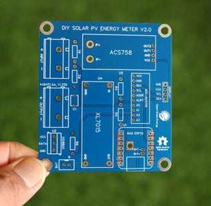
I have drawn the schematic by using EasyEDA online software and then designed a custom PCB for this project. The PCB is designed for mounting the different modules instead of using a lot of components. I ordered my PCB from PCBWay and received it within 7 days.
You can download the Gerber files from PCBWay
Step 9: PCB Assembly


For Soldering, you will need a decent Soldering Iron, Solder, Nipper, and a multimeter. It is good practice to solder the components according to their height. Solder the lesser height components first.
You can follow the following steps to solder the components :
1. Push the component legs through their holes, and turn the PCB on its back.
2. Hold the tip of the soldering iron to the junction of the pad and the leg of the component.
3. Feed the solder into the joint so that it flows all around the lead and covers the pad.
Once it has flowed all around, move the tip away.
Step 10: 3D Printed Enclosure


To give a nice commercial product look, I have designed an enclosure for this project by using Autodesk Fusion 360. The dimensions of all the components and PCB mounting holes are measured by a vernier caliper then the same were considered during the design.
The enclosure has two parts: 1. Main Body 2. Top Lid The
The main body is basically designed to keep the PCB board. The top lid is to cover up the main body opening and mounting the OLED display.
I used my Ender 3S1 Pro printer and 1.75 mm silver and pink PLA filament to print the parts. It took me about 6 hours to print the main body and around 2 hours to print the top lid.
My settings are:
Print Speed: 60 mm/s
Layer height: 0.2mm ( 0.3 also works well)
Fill Density: 20%
Extruder Temperature: 205 deg C
Bed Temp: 60 deg C
Download the STL files from Thingiverse
Step 11: Software and Libraries
To use the XIAO ESP32 board with the Arduino library, you’ll have to use the Arduino IDE with ESP32 board support. If you haven’t already done that yet, you can easily install ESP32 Board support to your Arduino IDE by following this tutorial by Sparkfun.
Install the Libraries:
Before uploading the code install the following libraries :
2. Blynk
4. One Wire
Step 12: Interfacing With Blynk 2.0


Blynk 2.0 is a versatile IoT platform that allows you to create custom dashboards for monitoring sensor data from your devices. This section will guide you on setting up both web and mobile dashboards in Blynk 2.0 using four gauges, two labels, and one graph.
Step 1: Setting up Blynk 2.0 Account
If you haven't already, first sign up for a new Blynk 2.0 account. Navigate to Blynk's website or download the Blynk app on your mobile device, then register for a new account.
Step 2: Creating a New Project
After logging in, you'll be directed to your Blynk account dashboard. Now you have to give a name to your Hardware ( Solar PV Monitoring V2). Choose the Hardware type as ESP32 and the connection type as WiFi. You can also write a shot of the description in the description box. Then click on Done. Now the template is created successfully.
Step 3: Adding Data Streams
For this project, I have used 6 data streams for voltage, current, power, energy, temperature, and savings. And assigned virtual pins from V0 to V5 for all the variables.
You have to also give the unit of measurement and minimum, maximum value for it. In our case, the voltage is assigned to virtual pin V0, the data type is Double, the unit is Volt, the minimum is 0 and the maximum is solar panel maximum voltage. You can also select the specific color of your choice.
Step-4: Adding New Device
Now we have to add a new device here. Select the device from a template that you created earlier. After giving a name to the device, click on Create. A device authentication token ( 3 lines in a black box at the top right corner) will be generated now. Make sure to save this Auth Token as it will be needed in your Arduino code.
Step 5: Creating a Web Dashboard
In the Web Dashboard, drag and drop 4 widgets Gauge, two labels, and one chart on the dashboard. Then click on the gear icon to set the parameters as shown below. Then save it and repeat the same process for setting up all 7 widgets.
After setting up the widgets, you can arrange them as you like by dragging and dropping. You can also resize them to fit your preferences.
Step 6: Creating a Mobile Dashboard
The process for setting up a mobile dashboard is similar to a web dashboard. After arranging the widgets, you can preview how the dashboard will look on a mobile device. Note that any changes you make on the web dashboard do not affect the mobile dashboard, and vice versa. You can customize each to fit your specific needs.
Step 7: Syncing the Project to Your Device
Now that your Blynk project and dashboards are set up, it's time to sync them with your Xiao ESP32. Use the Auth Token you received in Step 2 and include it in your Arduino code.
Step 13: Arduino Code
#define BLYNK_TEMPLATE_ID "TMPL3V-0wJfRH"
#define BLYNK_TEMPLATE_NAME "Solar PV Energy Meter V2"
#define BLYNK_AUTH_TOKEN "YOUR AUTH TOKEN"
#define BLYNK_PRINT Serial


#include <Wire.h>
#include <Adafruit_SSD1306.h>
#include <Adafruit_ADS1X15.h>
#include <BlynkSimpleEsp32.h>
#include <OneWire.h>
#include <DallasTemperature.h>


// Pin definitions
const int oneWirePin = D3; // OneWire pin for DS18B20


// OLED display
Adafruit_SSD1306 display(128, 64, &Wire);


// ADS1115
Adafruit_ADS1115 ads;


// DS18B20 temperature sensor
OneWire oneWire(oneWirePin);
DallasTemperature sensors(&oneWire);


float voltage =0;
float current =0;
float power =0;
unsigned long previousMillis = 0;
float energy = 0;
float temperature =0;
float saving =0; // cost saving
const float EnergyCost = 6.5;


// Voltage divider resistor values
const float R1 = 100;  // 100K
const float R2 = 10;  // 10K
const float R3 = 1;  // 1K
const float R4 = 2; // 2K


// ACS758 zero-current output voltage ( Offset Voltage)
float OffsetVoltage = 2.5;
// ACS758 current sensor sensitivity
const float sensitivity = 40; // in mV/A


//========================= Variables for wifi server setup =============================
const char* ssid = "XXXXXXX";
const char* password = "XXXXX";
const char* blynkAuth = BLYNK_AUTH_TOKEN;


void setup()
{
  Serial.begin(115200);
  // Initialize the Wi-Fi and Blynk connections
  WiFi.begin(ssid, password);
  while (WiFi.status() != WL_CONNECTED) {
    delay(500);
    Serial.print(".");
  }
  Serial.println("\nConnected to Wi-Fi");
  Blynk.begin(blynkAuth, ssid, password);

  // Initialize the OLED display
  display.begin(SSD1306_SWITCHCAPVCC, 0x3C);
  display.clearDisplay();
  display.display();


  // Initialize the ADS1115
  ads.begin();


  // Initialize the DS18B20 temperature sensor
  sensors.begin();
}


void loop() {

  // Read the raw voltage values from the ADS1115
  int16_t voltageRaw = ads.readADC_SingleEnded(0);
  int16_t currentRaw = ads.readADC_SingleEnded(1);


  // Calculate the voltage values in Volts
  float voltageVolts = voltageRaw * (0.1875/1000) ; //  0.1875mV is default Gain
  float voltage = voltageVolts * ((R1 + R2) / R2); // Calculate the actual voltage by using the voltage dividers

  // Calculate the current values in Amps
  float currentVolts = currentRaw * ((R3 + R4) / R4)* (0.1875/1000); //  0.1875mV is default Gain
  current =  (currentVolts - OffsetVoltage )/(sensitivity / 1000.0) ; // convert voltage into current

  // Calculate the power output (P = V * I)
  power = voltage * current;


  // Calculate energy by integrating power over time
  unsigned long currentMillis = millis();
  energy += power * (currentMillis - previousMillis) / 3600000; // Energy in Wh
  saving = EnergyCost * ( energy /1000 );
  previousMillis = currentMillis;


  // Read the temperature from the DS18B20 sensor
  sensors.requestTemperatures();
  temperature = sensors.getTempCByIndex(0);  // temperature in Celsius
//temperature = sensors.getTempFByIndex(0); // temperature in Fahrenheit

  //Display the values on the OLED screen
  display.clearDisplay();
  display.setTextSize(1);
  display.setTextColor(WHITE);
  display.setCursor(10, 10);
  display.print(voltage,2);
  display.println(" V");
  display.setCursor(70, 10);
  display.print(current,2);
  display.println(" A");
  display.setTextSize(2);
  display.setCursor(10,25);
  display.print(power,2);
  display.println(" W");
  display.setCursor(10,45);
  display.print(energy,2);
  display.println(" Wh");
 // display.print("T: ");
 // display.print(temperature);
 // display.println(" C");
  display.display();


  // ================= Display Data on Blynk App ================================================

  // Send the data to Blynk
  Blynk.run();
  Blynk.virtualWrite(V0, voltage);
  Blynk.virtualWrite(V1, current);
  Blynk.virtualWrite(V2, power);
  Blynk.virtualWrite(V3, energy/1000);
  Blynk.virtualWrite(V4, temperature);
  Blynk.virtualWrite(V5, saving);


 // Print the values on the Serial Monitor
  Serial.print(" Voltage: ");
  Serial.print(voltage);
  Serial.print("V");
  Serial.print(" Current: ");
  Serial.print(current);
  Serial.print("A");
  Serial.print(" Power: ");
  Serial.print(power);
  Serial.print("W");
  Serial.print(" Energy: ");
  Serial.print(energy,2);
  Serial.print("Wh");
  Serial.print(" Savings: ");
  Serial.print("Rs.");
  Serial.print(saving,2);
  Serial.print(" Temp: ");
  Serial.print(temperature);
  Serial.println("C");

  delay(100);
}
Step 14: Field Testing


Now our device is ready for real field testing. The connection shall be as follows:
1. Connect the negative terminal of the load to the negative terminal of the output screw terminal and then the positive terminal to the output positive terminal. Here I have connected the out terminal to my inverter solar input terminal.
2. Connect the Solar panel’s negative terminal to the negative terminal of the Input screw terminal and positive to the input positive terminal.
The Input and Output screw terminals can be used for wire sizes from 26 – 10AWG.
Note: Be sure you are connecting to the right polarity, otherwise you will see the magic smoke. The circuit doesn’t have reverse polarity protection.
After all the connections, you will see your solar panel parameters displayed on the OLED display. You can check it from your smartphone by opening the Blynk App.