

Introduction: DSLR Camera Mod: Plug in Power for Less Than $10


I have been running into a problematic issue with a photobooth that I made (the booth is on Instructables here). After a period of several hours, the crappy old camera battery peters out and dies. I purchased some cheapy replacements online but even those do not seem to last very long. This is a huge PITA because every time I have to change out a battery, it requires removal/reinstallation of the camera and recalibration (fixing camera pointing, correct zoom, proper focus). Who wants to do all that when you should be busy having fun?
I searched online but AC adapters for the camera cost between $80 for a legit Canon one to $40 for a cheapie. I decided to build my own. More recent searches turned up even cheaper AC adapters (in the $10-$20 range) but quality is obviously dubious. If I am going to invest in some potential crap, it might as well be some crap I kludged together myself!
Note that while I performed this hack for a Canon 10D, this work can be easily adapted for just about any digital camera.
Step 1: Parts
Parts Needed:
Scrap battery of appropriate size for your camera
Wall Wart (AC/DC adapter) - 12V DC output
2.1 mm plug to mate with wall wart
LM317 - adjustable voltage regulator
240 Ohm resistor (I used a 220 ohm and it worked perfectly fine)
5k Trimpot
Small piece of perforated board - get one with rails!
Tools You Should Have:
Small-bladed hack saw
Soldering Iron
Hot glue
Multimeter
Bench Supply
The tools listed above are just the ones I used. Feel free to substitute whatever you have that gets the job done. The work can be performed without a multimeter or bench supply but they are recommended.
Step 2:


Note, the battery should be fully drained before you begin this step or there may be some sparks and possibly a small shock.
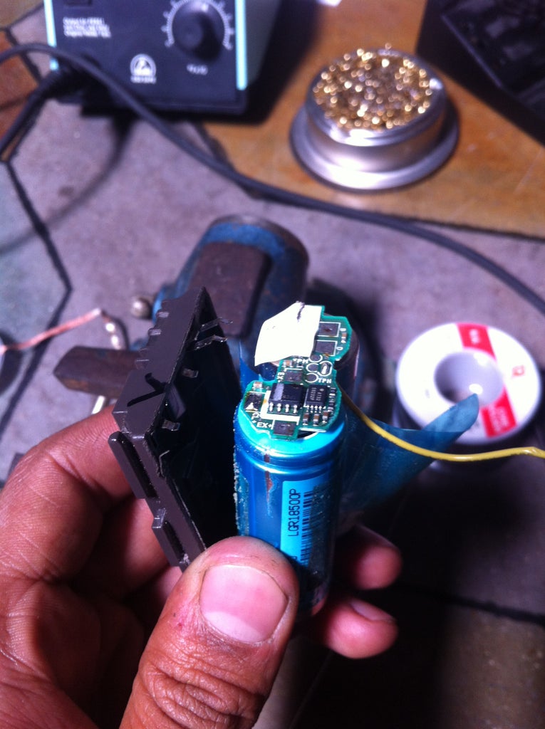
Begin by using the saw along the all four seams of the battery. A particular seam is done when you can see the battery or circuit board underneath (Pic 2). Also at this point, use a sharpie to mark both sides of the battery cover so that you can be certain of the orientation when you put it back together.
When all four seams are finished, you can pry apart the cover (Pic 3). There will be a adhesive gel holding things in place so a flathead may help here. Be careful not to destroy the plastic cover itself.
Use a soldering iron to desolder the battery cover's metal contacts from the circuit board (solder wick will help). The board is just used for charging the batteries so it is junk (plus it probably got a healthy dose of sawblade anyway).
Once the connections are done, the batteries and board should separate from the covers.
Step 3:


Some considerations need to be made concerning the power supply for your camera. The general idea is to have a wall wart feed voltage to a regulator (LM317) that is tuned to the exact voltage your camera needs.
First, check the battery for the voltage that it outputs. The battery for a Canon 10D puts out 7.4V (Pic 1). A LM317 has a minimum dropout of 3V so a 12V power source will work comfortably for the voltage needed.
For testing purposes, it is a good idea to breadboard the circuit first and make certain that it is outputting working (pic 2). I took screenshots of the relevant information from the datasheet (pics 3 and 4). The datasheet is also attached here in its entirety.
I put the circuit together using only a 220 ohm resistor for R1 (datasheet states 240) and a 5k trim pot for R2. The trim pot is adjusted as necessary to get the correct voltage regulation.
I skipped the protection diodes (make sure you don't ground the output) and left out the capacitors Co (transient response? Pffffff) and Ci.
I used clips to connect my circuit to the hollowed out battery shell, taped the two halves together, and tested it in my camera. It worked perfectly fine so I was happy with it.

Step 4: Make It (mostly) Permanent


Breadboards are appropriate for rapid prototyping but definitely not suitable for the field. A circuit properly placed on perf board can handle the rigors of the real world and typically last a long time.
Quick note on perf board selection: do yourself a favor and get a large board with rails. The board can easily be scored with a razor and snapped for small circuits. The layout should be similar to that of a breadboard (Pic 2). Perf boards that are laid out in separate squares (Pic 3) will end up a mess of solder blobs and messed up connections.
Once your circuit is placed and soldered up, be sure to test it again to make certain it is regulating the correct voltage. Adjust with the trim pot as necessary.
Cut the perf board to the appropriate size so that it will fit into the hollowed battery shell. Solder a wire from the regulator's output pin to the positive clip of the battery. Do the same from the circuit's ground to the battery's negative clip.
Drill an appropriately sized hole in the top of the battery so that you can have the 2.1 mm connector stick out flush with the surface of the battery. Use hot glue to fix the board and connector in place (Pic 4 and 5). Be certain that you also apply hot glue to any union between a wire and the board. When you are certain everything is in place correctly (and working correctly too) hot glue the two halves back together.
Drill a hole in your battery cover using a ruler to make sure that you place the hole in the correct place. Start with a smaller drill and step up in sizes until the adapter plug fits snugly in place.
Test it and have fun!
I have not used this rigorously yet but I have had my camera powered with it all day (more than 10 hours; auto power off is disabled; snapping the occasional picture to make certain it is still performing properly). It has worked continuously, flawlessly and only fairly warm when I checked the battery for temperature.


