

Introduction: Divisadero Chair


The Divisadero Chair is piece exploring how 3D modeling software, 3D capturing, and 5-axis CNC milling can be combined to allow for a more sensitive use of materials. Traditional tools make squares and circles very well, and digital fabrication has made a huge mark in it's ability to make more dynamic, organic and complex shapes. I wanted to push on these tools not to make more intricate forms, but rather use more complex stock material - like the live edge of a slab of wood, using the digital processes to celebrate the natural contour, and remove as little material as possible.
The Divisadero Chair was made from a 3-foot section of a slab of claro walnut - including the live edge - with a small amount of locally felled elm to occupy the space in the middle.
The concept for the chair was primarily inspired by three main ideas.
- Bole Wood Floors makes wood floor boards by scanning thin cut lengths of wood sections, and then designers layout well-nested segments, which are thin just lightly trimmed to match each other. The video of their process is a must-see!
- Allan Wexler has done a series of pieces of furniture which have been separated from their normal geometries - for instance a table cut into halves or quarters - and the relationship of the pieces is defined by how it is cut.
- A recent interview with Dieter Rams by FastCoDesign. Something in that interview, combined with these other ideas, led me to think that a kind of corallary to his 10 principles of good design is an implicit 11th principle: touch the material as little as possible.
This got me really excited to try to use the cutting edge digital fabrication tools we have at Pier 9 along with Autodesk software (123D Catch, Meshmixer, Inventor, Fusion, HSM) to explore new processes ways of making things that use all that high powered computing power and precision to optimize material usage. Rather than trying to create the wildest form from the plainest material, I was starting with an unusual starting material to make a rather straightforward form - an armchair.
Thanks for taking the time to read!
More of my work is on my website as well.
Step 1: Rough Chair Design

I allowed the design of the chair to remain fairly simple. There were a couple different types of joints I wanted to try making via CNC, as well as trying to embed as much of the complexity of angles in one piece - the armrest. I sketched out a few basic options before moving forward with my favorite. I drew these sketches to scale so that I could estimate the amount of wood I would need to execute the design, already taking into account the thickness of the slab, which was about 3".
Step 2: Laying Out Chair on Slab


Before I could lay out my chair, I had to remove the bark from the live edge so that I could reference the solid outer dimensions of my slab.
With the bark gone, the big challenge was accounting for the steep angle at the edge of the slab, since the cut was taken from the edge of the tree (as opposed to the center), the edge pieces' widths varied a lot from the top of the slab to the bottom.
I did my best to approximate where each piece would be taken from, so that when I cut the slab, I wouldn't waste any material, but would have just enough for the chair. The seat and back were drawn out slightly longer than necessary to accommodate design changes, and to leave room for me to pick the nicest continuous section, since I wanted the grain to be continuous from the seat onto the back.
With the rough layout done, I could refine my design a little bit further, with some more specific parameters around what wood I had to work with.
Step 3: Detailing Design in Fusion


I quickly sketch out my design in Autodesk's Fusion 360, basing my geometry on simple angles transcribed from my scale drawings. This allowed me to see my chair a little better in 3D, and to start to lay out the joinery. Fusion was a great way to lay out the design really fast, with an accuracy that allowed me to go confidently into the woodshop with solid dimensions.
From Fusion, I wrote down a cut list, which had everything down to within 1/8" of where I would finally need it. With that information, I measured out a careful layout in red on my slab.
Step 4: Milling Rough Blanks


In order to prepare for 3D capturing and machining, I had to break the slab into the component pieces that would make up the chair. This all happened with traditional woodshop tools - a circular saw, bandsaw, jointer, planer, and tablesaw - which I used to make all the square cuts I could, leaving the organic edges neatly oriented and ready for 5-axis machining.
First, I made a circular saw cut in the wood (the slab's thickness meant I needed two cuts, top and bottom) in order to break the slab into a manageable size for me to work with on the other tools.
Then, I laid out a careful, length-wise guiding line for a bandsaw cut, which would define the rectangular orientation for the rest of the square cuts I would make. I followed this cut with a quick jointing just to clean up the surface, then ripped the other side on the table saw to create three separate pieces. The middle was the bulk of the body of the chair, the sides with live edge would become the seat and the back.
I planed these down to thickness, and then split the live edge sections into manageable sizes for 3D capturing and towards the final thickness of the seat and the back.
Here I even waited to finish milling the seat and the back to make any final length cuts until I had gone through the process of 3D capturing and live edge machining, in case anything caused problems in that process.
Step 5: 3D Capturing


I had a lot of material for the seat and the back. I was unsure how the process would work, so I left extra. It turned out to be a little less than double what I needed. So I accommodated the process by just dividing it into two batches, which turned out in the end to be a lifesaver, after the seat was damaged in the finishing process.
I labelled each piece with blue tape to help keep track of grain continuity, and had the added benefit of appearing subtly on the surface of the 3D capture, helping to match the digital files to the pieces of wood in the physical world.
Using 123D Catch, I scanned each of the pieces in a bright, open room with the live edge facing straight up, just using my iPhone. The software captured all the detail I needed on the piece, as well as the area around it. You can even see the tape - which registers not for it's thickness, but for it's color. I've found blue scans very well.
Step 6: Editing 3D Live Edge Captures


With the raw files saved into the cloud, I followed a digital workflow that I have worked with a number of times here at Pier 9, which I outlined in this Instructable.
This process removes unwanted data, adjusts mesh density and outputs a solid STL from Autodesk's free software Meshmixer, which is further oriented, scaled, and healed in a free application called Netfabb, before being imported into Inventor and converted to a solid using the Autodesk subscription Inventor plugin, Mesh Enabler.
From there, I found the variance of the angle of the live edge and created a new workplane normal to the board but biased at the angle of the average angle of the edge. Then, I made a spline sketch of the edge contour, and made an extruded cut into the mesh to create a clean, smooth surface from that sketch. After double-checking dimensions, I added the two opposed live edges that would make up each the seat and the back, and extruded a boolean of those forms using the exact same sketches and workplanes in a new solid. This way, I created the negative of the two live edges, with all surfaces being perfectly smooth and matching perfectly - necessary for a good glue-up.
I used HSM inside Inventor to CAM the part so that the length of the cutting tool would be engaged with the surface all at once, making thin radial offset passes to clean up the live edge, rather than machining it with a stepover strategy that would leave small ridges behind. You can see the tool path for that contour toolpath in one of the images above. The negative space for the seat and back middle pieces required a roughing pass as well.
Step 7: Machining the Live Edge


The live edge of the claro walnut was machined to remove the bare minimum material, which was just a light, fluffy handful of shavings for each board. By keeping the live edge intact, the process preserves a huge amount of wood that would be wasted in the process of making any traditional section of wood, be that a square board or veneer or plywood.
The lighter wood is elm that was already milled square, and a small amount of material was removed there to match the natural walnut edge.
For some reason, I was shocked at how well the pieces fit together (as seamless in person as they appear in the photo).
Step 8: Laminating the Live Edge Pieces Into Solid Blanks


Here's where I got into some trouble. I was a bit sloppy using loose, custom biscuits to strengthen joint between the organic surfaces. I lost track of depth relative to this biscuit during planing, flipping the part back and forth, which meant that later, when I machined the seat into the board, I cut close to the air pocket at the edge of the biscuit. I shouldn't have left air in their, regardless.
So here, I glued up the pieces, then trimmed off the extra material so that I had clean blanks to machine into my seat and my back.
I altered the design for the second round, opting for tighter-fitting, deeper dowels to strength and register the seam.
Step 9: Detailed Design and CAM in Fusion With HSM


This step just details the design a bit more, shows how the joints were modeled, and a little bit of the CAM toolpathing. I used Fusion with HSM for this part of the process - it's such a flexible and quick program, lightweight in the best sense of the word for the work I was doing. The construction in one entire model made it much easier to copy CAM setups and operations from one part to it's mirrored mate (ie front left leg to front right leg), which was a huge timesaver.
There were something ridiculous like unique 150 CAM in 24 separate part setups/orientations. Most of these were very quick - but unless CNC is being used for a reasonable sized batch (10+ units), it's really not a whole lot faster than doing it by hand! But it was great for making the super complex armrests, which accept tenons at 90 degrees to the legs that they mate too. And also good practice fixturing, and visualizing part setups and machining strategies.
I'm not going to narrate the machining. I'll let the pictures tell the story!
Step 10: Machining the Seat and Back


Thanks to the 5-axis capabilities of Pier 9's DMS router, I just had to dance the clamps around the joints and carving for the seat and the back. Once the piece was loaded and fully tightened down, it didn't move until all the operations had been run.
Step 11: Machining the Arms


The arms were designed to have the most complexity, so that they could be machined using the DMS and then hypothetically all the rest of the pieces could be easily cut by hand using traditional woodworking tools and right angles. The arms are fully sculpted, and have three different joints cut into them, all at very precise, non-normal angles, which made the DMS the best tool for the job.
Step 12: Machining the Legs


For the legs, I machined the various pieces of joinery all in one clamping, so that all the critical dimensions were perfectly referenced to each other. Then I used this massive, expensive machine to trace a thin cut where I then removed the excess material by hand, leaving just enough to load back into the machine for a final cleanup.
By removing the part from the machine, I avoided the risk (high risk) of tear out as the end mill hogs out such a large amount of excess material along the grain direction. It also might have even saved a minute, considering I needed to flip the part anyway.
Step 13: Machining the Back Supports, Crossbars and Aprons


At this point, I committed to making all the parts on the CNC, just for fun, because I could. It would have felt a little weird to be cutting tenons with a hand saw in the room next door. You can see in the photos that the 5-axis capability kept coming in handy.
Step 14: Assembly


Before doing any sanding, I glued together the main frame of the chair, so that all my finishing work would leave flush, seamless surfaces. I tested each joint in the machine, and made adjustments before I removed anything from the vise in the DMS, so I had really nicely fitting joints when it came time to assemble.
Step 15: Finishing


Here I reconciled some of the small offsets between the shoulders of a tenon and the cheeks of a mortise, first shaving and then scraping or sanding the features all to be soft and flush. I removed the last of the machining marks with a spokeshave and scrapers, before embarking on one last sequence of sanding, ending at 400 grit before applying Danish oil.
With one coat of oil carefully applied to everything but the joints, I glued together the remainder of the chair before applying the final coat.
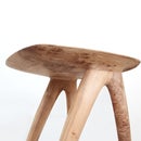
Step 16: Divisadero Chair


The Divisadero Chair is just a showcase for how digital fabrication workflows - from capturing and modeling software to 5-axis CNC machining - can support more sensitive processing of unusual materials. Much has been made of the incredible new shapes we can make appear seemingly out of thin air using new digital techniques. Many of these are brilliantly optimized around naturally occurring structures, repetition, and even finite element analysis.
Divisadero represents another line of inquiry into the future of digital fabrication. Rather than searching for how we can make more exotic or complex forms, the focus here is using smarter tools to start with more complicated starting geometry, remove less material, and expose natural beauty that in the past was simply removed for the sake of precision.


