

Introduction: ESP8266 Based Web Configurable Wifi General Purpose Control (Part III)


NOTE: Ready to go boards can be purchased here
The electronics part
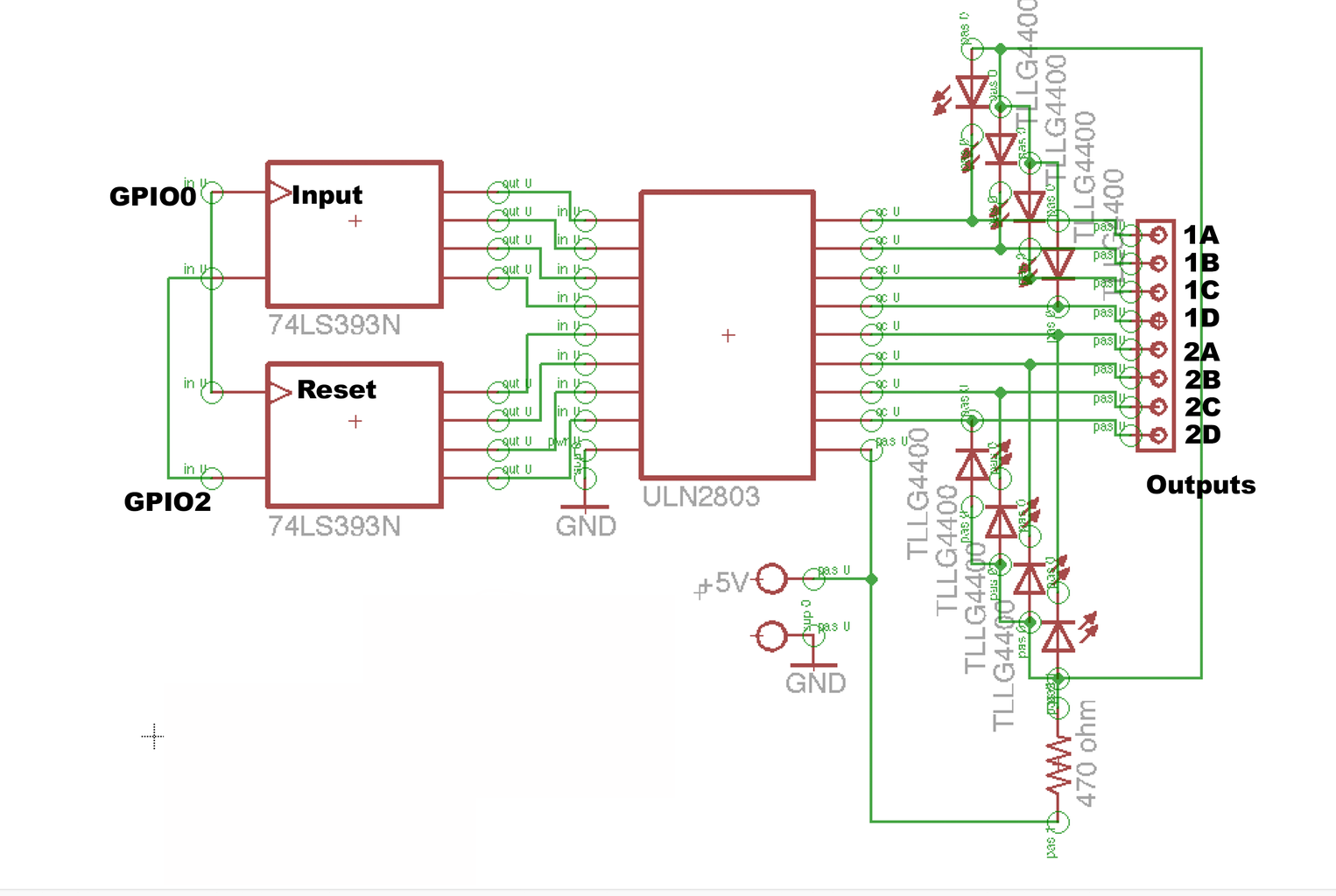
In Part I and II we saw how to program and remotely configure the ESP8266 to turn it into a processor of TCP events and use GPIO to communicate with the world. Now we will take those events and turn them into something useful by controlling a set of switches. We start with a dual 4 bit binary counter, 74LS393N. This chip has 2 full 4 bit binary counters.
We will connect the inputs together and the resets together. GPIO0 from the ESP8266 will be connected to the inputs and GPIO2 to the reset. The output of the 393 will go into ULN2803 which is a 8 x darlington driver. The 2803 will drive relays or any other low power stuff. A set of leds will indicate which output is on.
Now when a TCP GPIO High/Low event is sent to the module IP address port 9999, this event will be redirected to the binary counter. The process is as follows:
a low/high event on GPIO2 sent to the port will reset the binary counter
a low/high event on GPIO0 sent to the port will count once
an ‘n’ low/high events on GPIO0 sent to the port will count ‘n’ times
with this arrangement we can count to 16 on each 1/2 of the binary counter
we will use each of the 4 bits outputs to drive a signal (led, relay, etc)
one low/high events on GPIO0 will turn on output 1A and 1B
2 low/high events on GPIO0 will turn on output 2A and 2B
3 low/high events on GPIO0 will turn on output 1A, 2A, 1B and 2B
16 low/high events on GPIO0 will turn on all outputs
a low/high event on GPIO2 will reset the binary counter and turn off all outputs.
For the complete description of the project visit www.horaciobouzas.com


