

Introduction: Easy Modular Magnetic Desk Lamp


Hi, we are a couple of college students that are passionate about lighting and electronics. We believe that lighting fixtures should be different and we always like to challenge ourselves to make a solution that helps to make usual everyday light modern looking, modular and easy to use. We got inspiration from HHarry's project (https://www.instructables.com/id/Magnetic-table-lamp/), but when we tried to build something similar, we ended up struggling a lot to make everything precise enough to fit it together nicely and so it could be used in modern house design.
How many of you daily pay attention to the surrounding light quality? How many of you seem to have vision problems because of insufficient lighting? And then the choice of lamps is a complicated and long process because there are so many options.
Our main goals to achieve with this project was to get:
- high color rendering index,
- easily customizable design,
- and portability.
This is not going to be an easy project, but we tried to do our best to make everything as easy as possible at the same time-saving quality and precision.
Step 1: Materials and Tools


Materials for 5 cubes, small and big base:
- Ash 4000x1500x15mm - glued / finger joined for big base
- 32 ash wood cubes 101x101x10mm for cubes and small base
- 96 rivets M3x8mm - https://www.aliexpress.com/store/product/100Pcs-M...
- 120 metallic locks for fixing a glass
- Acrylic glass frosted 480x400x2mm
- 95 magnets 6x3mm - https://www.aliexpress.com/store/product/100Pcs-M...
- 3 magnets 6x5mm
- 3 mother connectors 5.5x2.1mm - https://www.aliexpress.com/store/product/100Pcs-M...
- 1 touch dimmer (for big base) - https://www.aliexpress.com/store/product/100Pcs-M...
- 1 built-in touch dimmer (for small base) - https://www.aliexpress.com/store/product/100Pcs-M...
- 1 touch switch in the wire (for 3D printed connector) - https://www.aliexpress.com/store/product/100Pcs-M...
- 1 mosfet - https://www.aliexpress.com/store/product/100Pcs-M...
- 1 USB step-down - https://www.aliexpress.com/store/product/100Pcs-M...
- 1 step-up with micro USB - https://www.aliexpress.com/store/product/100Pcs-M...
- 5 resistors 2.2ohm - https://www.aliexpress.com/store/product/100Pcs-M...
- 1.5m LED strip (I use 2835 240leds/m) - https://www.aliexpress.com/store/product/100Pcs-M...
- 1 power adapter 8A (for big base) - https://www.aliexpress.com/store/product/100Pcs-M...
- 1 power adapter 1A (for small base) - https://www.aliexpress.com/store/product/100Pcs-M...
- 11 rubber feet (8mm diameter)
- 3mm plastic tube for big base
Tools:
- Hand mill (copier, 45 °, straight)
- Stationary drill (2, 3, 6, 24, 64, 74mm drill bits)
- Bandsaw
- Electronic screwdriver + 90 ° adapter
- Sander
- Sandblast
- Soldering iron (30W, 100W) + tin, etc.
- 12V Power supply, multimeter
- PVA glue, 2 component epoxy, hot glue gun
- Riveting tool - we made one ourselves from 2 woodworking awls
- Hammer
- Caliper
- Stencils - it is possible to order them from the local factory from steel as we did, but still gonna work out if made from plywood at home (dimensions attached)
- 3D printing + PLA material
- Ash color filler/putty for wood
- 2 cans of varnish
- Wires
- Anti-static spray - to protect the acrylic glass from sticking dust and give it a glossy look
- Painter tape, double-sided tape

Step 2: Preparing Material


In this tutorial, it is going to be showed how to make just one cube, but usually, we make 5 - 8 to fully enjoy modularity and design of the lamp.
To start you will need to make 101x101x10mm workpieces (6 for each cube) out of ash or oak.
Really important is to keep good track of all workpieces where you put them and in which order, because when you make 5 cubes it is easy to screw up to which workpieces you need to do what.
Step 3: Stencil & Hole Drilling


We made 3 stencils out of 6mm steel, but you can make them from the same wooden workpieces as well. Dimensions are attached. One is with a big central hole in the center for milling, second is with 4xM5 threads for marking and third with 3x3mm holes and plastic attached for 45º milling.
First stencil with 4xM5 threads you need to insert 4 screws with sharpened ends, then center it on the workpiece and with a hammer easily make marks for drilling.
Not to mess up which side is going to be outside and which inside of the cube, you can mark the back side with "B" (backside). That is the same side where you make marks with a stencil.
First, you need to drill 3x3mm drills for rivets all the way through. When you start to drill let workpiece a little bit loose so that the drill center matches the mark from a stencil.
After that, you take 6mm drill and grind it with a hand drill and sandpaper to approximately 5.9mm diameter. It is to make 6mm magnets hold tight. And then make 5.9mm drill from the backside so that full diameter is 1mm deep.
Then take a 64mm drill and make 4 gaps with an angle grinder as in the picture. It improves cooling, lets the chips fly out so that the edges are not burned. And keep in mind to make this drill with speed, not more than 1000rpm.
When you clamp the workpiece in the jaw, don't overtighten them, because the workpiece can crack and then it is not going to be usable anymore.
Step 4: 45° Side and Big Hole Milling With Stencil


Then you take the second stencil with 3x3mm bores and stack it together with 2mm piece of plastic. This helps to save the mill from damage if you accidentally make mistake and try to mill too deep.
Then stack together stencil with the workpiece and adjust the necessary height. Mill all 4 sides 45° by doing 3 tours over each side and at the end one final lap to smooth everything out.
We made a modification to our 19mm endmill - switched from 626Z bearing to 2x 10x6x3mm bearings to get that groove. And also we made carriage to simplify milling. Dimensions are attached.
Take workpiece and put it into the carriage with stencil and mill around the central circle. Do it counterclockwise of mill rotation.
Step 5: Inserting Rivets


Inserting rivets is an easy process. Take 2 awls and sharpen the end of it by rasping it with round rasp like in the picture.
Then insert flat awl in the jaw and tighten them. Insert rivet from the top side of the workpiece and with help of the second awl and hammer lightly insert it in the place.
Don't do it too hard or the rivet is going to split and later get loose.
Do it with all 18 rivets and at the end rasp the middle rivets of from the 45ºangle side so it doesn't obstruct gluing process later.
Step 6: Gluing Cube


Line out 6 workpieces so that they match schematic in the picture so you won't mess up anything.
Take wooden glue and brush. Apply glue on the first 4 workpieces that are going to make sides of the cube. Then try to put them together. Do it fast so the glue doesn't dry.
When all 4 workpieces are holding lightly together, take painters tape and start to wrap around the cube. At the first do it without force just to get all workpieces to hold together and the slightly increase force how strong you tighten workpieces together.
The reason why we use painters tape because it is cheap and when we tried to use jaws it was very easy to get them too tight and then the cubes will come out more like rectangular parallelepiped.
Then take 5th workpiece, apply glue on it and all 4 sides where you are going to place it and put it in place.
Also, take 6th workpiece but don't put glue on it, because later we will solder the light cube inside through that spot. Put it in just to wrap painters tape around and there are no sharp edges.
Apply painters tape to all 3 dimensions and then with the help of fingers straighten the cube by pressing edges and corners together if that is necessary.
Let the cube sit there for one day.
Step 7: Fine Grinding, Smudge Repairing & Varnishing


When the glue is dry take all painters tape away. Take unglued workpiece off and check is everything nice and straight. Then take sandpaper (120 and then 200) and go over everything in the following order - start with circular holes (look for smudges, burns from the mill or sharp edges) then continue with all the faces (look for glue surpluses and defects in wood structure) and finish up by making going lightly over all edges except 4 edges where cover is going to be.
When you sand faces do it in the same direction as fiber goes or you will scratch the wood and then it is going to be really hard to get those scratches out.
After you have completed sanding, try to look is there some cracks in wood or empty places between edges where is no glue - if you find something like that, just take wooden putty in the same color as your wood and with finger put it in the empty gaps. Then with the help of white clout quickly clean up unnecessary putty before it is dried. Repeat this process until all empty gaps are full. Then wait for the putty to dry and sand it lightly with sandpaper.
When the cube looks good, cover rivet holes with something. We found out that the easiest way is to use sticky reusable adhesive gum. Then take a colorless acrylic varnish and apply it to the cube and cover workpiece. Don't forget about insides or circular holes. Usually, we apply two to three layers of varnish.
Step 8: Wire Preparing & Pre-soldering


In this step, you will need to cut 1mm2 thick wire in different lengths and solder them into rivets. All given wire length are approximate and can change so keep an open mind and see what fits for you the best.
For "+" wire you will need to leave isolation on and cut them in 3 different lengths:
- 7.5cm L shape wires 3 pieces
- 15.0cm Z shape wire 1 piece
- 9.5cm U shape wire 1 piece
And for "-" wire you can strip isolation off to save some space and weight. And the lengths are:
- 8.5cm L shape wires 6 pieces
- 9.5cm I shape wire 1 piece
- 4.0cm Ω shape wires 4 pieces + 1 piece 3.0cm
- 14.0cm I shape wires 2 pieces for light cube
So the idea here is to solder all "+" together and then all "-" of the cube. "+" is going to be all the magnet places on the side where is only one magnet (so 6 magnets together) and all "-" are going to the sides where are 2 magnets in a row (18 together).
Hopefully, pictures are going to help visualize how wires are soldered.
Step 9: Acrylic Circle Drilling, Sanding & Insertion


Take 76mm drill and remove the middle drill so that it doesn't make a hole in the middle of the circle. Then go ahead and drill 6 round acrylic pieces for each cube.
NB! Don't peel off the protective layer of film. We will do it later.
After you have done that, take sandpaper and smooth all edges so that you can't harm yourself and the acrylic circle fits into the workpiece.
Then take the metal fasteners and with metal cutting scissors cut off all 3 extensions. After that fasteners should look the same as in the picture. And then with the help of pliers make a slight dent in the middle part to make some tension when holding the acrylic circle in place. You will need 4 fasteners for each side of the cube, so total 24 for each cube.
Then drill 4 holes on the backside of each workpiece.
Take acrylic circles and one by one peel off protective layers of both sides and spray on an anti-static spray to protect it from small dust.
Then secure circles in place with 4 screws. First, screw in the sides and only then the bottom side.
Step 10: Light Preparing (soldering) & Insertion


Cut the light strip so that each piece have 18 LED's on it (approximate 7.5cm long). For each cube, you will need 4 strips like that.
Solder them together in pairs so that the "+" is in middle and "-" at the outside. And add 4 resistors (no matter what kind - they will be used as joints only) as in the picture. And then fold the strip that each side have 12 LED's in total.
Solder 2 pieces like that together and add "+" wire from one to another.
Then cut 2 wires around 17cm long and add solder small tin points at 2 spots (around 6.5cm and 10.5cm). Then put it inside of the cube which is made out of LED's strip and solder both of them so they make X pattern across the cube. These are going to be "-" leads.
Then add a 2.2ohm resistor to "+" of the LED cube - it will be our "+" lead.
Put 2 strips of paper inside our wooden cube so that you are not ruining acrylic glass while soldering. Fold all 4 ends of "-" leads in a hook shape and insert it in the wooden cube so that all hooks goes inside the loop.
Then align the LED cube so that it is in the center of the wooden cube in all 3 directions and solder "-" leads to loops. Solder also resistor to "+" wire from the wooden cube.
Take out the paper and once more with the help of cotton wool and anti-static spray clean all acrylic circles from inside of the cube.
At this point make sure there is no soldering tin left on the walls of loose solders - because if there is it will make sound inside the cube after closing.
Then solder the cover of the wooden cube in place.
Step 11: Cleaning, Testing & Final Gluing


Take 12V power adapter and check is everything working correctly and there is a connection to all 18 magnet places and cube turns on.
Check carefully because once you will glue cube together there will not be an option to open it once more and fix the faulty connection.
If everything works fine then glue the cover to the wooden cube.
Once the glue is dried lightly go over the edges with sandpaper and putty. Then with the cloth apply a light coat of varnish on the edges.
Step 12: Magnet Insertion (gluing)


You will need 18 6x3 magnets for each cube. Group them in two parts - half of them we are going to glue with Z pole upwards and another half so that the S pole is up.
Go with the sandblast over the magnets so that shiny coat of zinc is removed. This will help to glue the magnet to the rivet.
When the sandblasting is done, spray degreaser over the magnets. Then mix two-component epoxy and apply it to the rivet and hole where the magnet will sit.
Then with the help of drill press and flat screw press the magnet inside hole applying some force. But important is that the magnets stay around 0.2mm above the wood.
Always make sure that you are putting the magnet in so that the sanded part goes inside the hole not another way around.
And the system with the poles of the magnets are easy - 3 full sides of wooden cube go with one pole upward and the other 3 side goes with magnets another way around. Just make sure that opposite sides of the wooden cube have different polarity magnets.
And with the other half of magnets, you will need to use some kind of pad under wooden cube so you are not pressing also magnets from the bottom side of the cube deeper. We used just one of the wooden workpieces with 3 bigger holes drilled.
When all the magnets are glued in place, without waiting to glue to dry go to the power supply and once more check is there a connection with each magnet. If there is not - just go to drill press once more and put a little bit more force on that magnet. Just make sure that you always leave a slight mart of the magnet outside of the hole so that 2 cubes can stick together.
Step 13: Material for Small Base


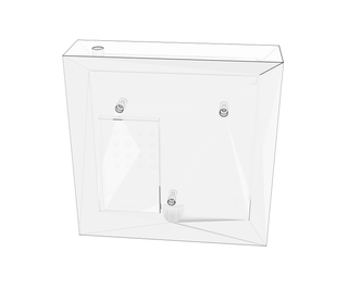
Now your cube is done. The only thing which is left is to build the base station. There are 2 options for that - small base which can handle up to 3 cubes and the big base where you can stack up to 8 cubes. And then there is also an option to 3D print adapter and stand for just one cube.
For both bases, the building process will be self-evident if you have already built at least one cube so we will not go into small details about that.
Let's start with a small base. Print out the stencil for small base milling, glue it on to the two workpieces just the same as for the cube.
Before milling drill all necessary holes starting with smaller ones. All measurements will be in Fusion360 file which is attached.
When drilling is done, mill everything that is in white color and with the help of small wooden file make room for the USB connector.


Step 14: Small Base Electronics & Assembling


Take all the electronic part and solder them together as shown in the schematic. Just make sure that the wires are long enough to reach all the places.
Inset rivets just like we did it to the cube. Then solder all the part in place and add a short 3mm plastic tube to the touch switch (we used one from LED shoelaces). Check that everything goes into their places and when you put both wooden pieces together that the touch switch is working. There won't be an option to correct the mistake if it is not enough sensitive to catch your touch. If it is not working at this point just remove some wood from the inner side of the wooden wall to make it more sensitive.
Then with the same epoxy glue USB board, DC connector and touch switch in place. And with PVA glue both wooden pieces together.
Wait for the glues to dry and then with sharp knife cut of the unnecessary plastic tube. Sand everything and fill the gaps with putty. Sand once more, close the rivet holes and apply varnish.
Then sandblast 3 more magnets the same polarity and glue them in the place.
Attach small rubber feet at the bottom corners.
Make a final check with a multimeter that everything is working correctly before attaching cube or something to the USB output.
Step 15: Material for Big Base


The big base station is a little bit complicated to build than the small one.
Before you start you will need to make 5 templates for milling (1 - 150x150mm & 4 - 150x40). When you have then with the double-sided tape glue them on the wood plate that is 10mm thick.
Then saw around templates leaving some space - make sure you don't saw in the template or this piece will not be usable anymore.
Then mill around a bigger piece with 45° mill and 3 sides of all smaller pieces. After that make forth side of all small pieces straight with regular copying mill.
After that remove templates and mill gap for mosfet on the bottom side of the bigger piece. Once again, all measurements you can look up in attached Fusion360 file.
When that is done, glue all pieces together with PVA glue and the help of some painters tape.
When the glue is dried, go over everything with sandpaper and drill all necessary holes for magnets, rivets, touch switch and connectors.
And then glue small 10x10mm wooden pieces in corners where bottom cover later will be attached.
Then print out the template for bottom cover, glue it onto 3mm plywood and drill all holes for ventilation and screws.
After that is done, cover rivets with something and apply varnish to the base and bottom cover.
Attachments
Step 16: Big Base Electronics & Assembling


Screw and solder everything together just like in schematic. Remember that for the touch switch the wire with female connector is input and male connector is output. Mark it somehow so you won't mess them up later.
Check that everything is working as it should - USB outputs 5V and touch switch activates mosfet and outputs 12V.
Insert rivets. And solder thicker wires to them (the same thickness we used in the cubes).
Glue 3 more magnets (the same polarity) in the places.
With the help of hot glue gun glue everything in place and screw on the bottom cover. Attach small rubber feet at the bottom corners.
Make a final check with a multimeter that everything is working correctly before attaching cube or something to the USB output.
Step 17: Additional 3D Printable Accessories


There is an option to 3D print a stand and L type connector to use just one cube.
- Stand - https://www.thingiverse.com/thing:3638570
- L type connector - https://www.thingiverse.com/thing:3638587
To the stand, you will need to attach 3 rubber feet (8mm diameter) under it.
For the L type connector, you will need to glue in DC female connector with 2 wire soldered to it and also 2 sandblasted 6x3 magnets with the same polarity.
Step 18: Resources and Future Plans


We want to say thanks to all our supporters who helped to make this project a reality!
- Jelgava Spidola State Gymnasium
- Jelgava Secondary School of Technology
- Junior Achievement Latvija
- Riga Technical University IdeaLAB
- University of Latvia Business Incubator
- Jelgava city
If there will be a time we are going to release 2nd version of this lamp with some major upgrades over building process with CNC machine and wifi connectivity to the lamp.
The team behind this project:
- Ralfs Rogalevs
- Ivars Bahmanis
- Aleksis Steinburgs
- Elina Sargune
- Elgars Rihards
- Toms Sutris
But so far if you have any questions feel free to comment. And let's make something cool!

Participated in the
Woodworking Contest


