

Introduction: Eclips3D2 3D Printer Assembly Guide


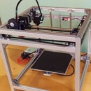
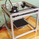
Meet the Eclips3D2. The (arguably) highest quality, best looking, highest performance consumer 3D printer for less than $3000. But you already knew that, didn't you? ;) Ok maybe you didn't, but now you know! Lets get right into things!
Head on over to www.eclips3D.com for all the info about this printer. The printer is open sourced, and you can download everything you need to get started here!
Please note that this instruction guide is not yet complete, please go forth at your own risk! The guide will be completed over the next few weeks, but feel free to email me directly at 3dprintedlife@gmail.com if you have any questions during your build. I am not responsible for any damage caused by this printer or any components of it. By building your own 3D printer from this kit, you assume all responsibility for anything that may occur. Please be careful and happy printing!
Step 1: Overview


This step is actually a step, believe it or not! Basically, this step is just a ton of pictures of the Eclips3D2. And why? Because you should have a good idea of what you're building before you actually build it. No but seriously, this will help you have a better understanding of where parts go as you build each sub assembly, and this will greatly help if you ever get confused during a step. Always keep the end goal in mind. Good luck!
Step 2: Y Gantry Assembly Part 1


Parts Needed
1x B4 - Y Gantry
2x D4 - M3 x 14mm SHCS
2x D8 - M5 x 14mm SHCS
2x D18 - M3 Washer
4x D19 - M5 Washer
2x G3 - Idler Spacer Short (3x5x10mm)
2x G6 - GT2 Idler Pulley
4x G9 - F625ZZ Bearing
Assembly
1. Assemble the 4 idler assemblies. There are 2 pairs of each type.
a. The first idler type uses bolt D4 as the post. First insert one washer D18 onto the bolt. Then slide on G3 idler spacer. Next, add G6 idler over the aluminum tube. Finally, add one washer D19. This washer should go around the tube as well.
b. The second idler type uses bolt D8 as the post. Slide 2x bearing G9 onto the bolt, ensuring the flanges face away from each other. Then, add one washer D19 to the bottom.
2. Attach idler assemblies to Y Gantry B4. Idlers of the same type will be mounted to the same face of the plate. Take special notice of the last picture, which shows the position of the idlers relative to the only hole on this part which is not symmetrical.
Step 3: Y Gantry Assembly Part 2


Parts Needed
1x D4 - M3 x 14mm SHCS
1x G3 - Idler Spacer Short (3x5x10mm)
Assembly
1. Assemble the endstop post by sliding the idler spacer G3 over bolt D4.
2. Attach the endstop post assembly to the Y Plate. It goes into the same hole mentioned in the previous step. Take notice that the post is mounted on the same face of the plate as the gt2 toothed idlers.
Step 4: Y Gantry Assembly Part 3


Parts Needed
1x F1 - Hiwin 250mm Rail
6x D3 - M3 x 8mm SHCS
Assembly
1. Insert 6x bolt D3 into the holes of linear rail F1 for prep.
2. Place the linear rail on the Y Axis Plate and align bolt holes. Screw in all the bolts very loosely. Note orientation to ensure the linear rail is not installed on the wrong side. It should be on the opposite face as the endstop post from the previous step.
3. While pushing the linear rail down, snug up all of the bolts. This is to ensure the linear guide is perfectly parallel with the Y Axis Plate. Once all the bolts are snug, go back and tighten them all down tightly, but not gorilla tight.
Step 5: X Carriage Assembly Part 1


THIS STEP WILL BE CHANGING WITH THE UPDATED GANTRY IN V2.1
Basic assembly is the same, although the new x gantry plate looks slightly different (it has a slot instead of a funky looking hole. Also, use the longer black flat head bolts (8mm long) for attaching the two machined pieces together. Use the short 4 for attaching the x carriage plate to the linear guide.
Step 6: CoreXY Linear Rails


Parts Needed
1x B1 - Top Plate
2x F1 - Hiwin 250mm Rail
12x D3 - M3 x 8mm SHCS
Assembly
1. Place linear rails F1 onto base plate B1. The 10 holes in the linear rail should line up with the threaded holes in the base plate.
2. Insert 6x bolts D3 into each linear rail. Take note of the bolt pattern, not all holes are used.
3. Loosely screw in the bolts. You should still be able to easily shift the linear rail. The bolts will be tightened in a later step.
Step 7: CoreXY Motion Control


Parts Needed
8x D13 - M3x40mm black SHCS
2x E1 - Nema 17 48mm
8x G4 - Motor Spacer (3x10x30mm)
G7 - GT2 20T Drive Pulley
Assembly
1. Prepare the two stepper motors D13 with G7 drive pulleys. Note that one should be facing up and the other down. Their exact position is not important and will be adjusted later, it's better to mount them low for now so they don't interfere.
2. Note which side each motor goes on. Keep in mind we will be flipping the plate, so make sure the motor follows the side it should be on.
3. Starting with the left side (when looking at the plate from the orientation in picture 4) prop up the top plate with your hand. Place the appropriate stepper motor under the plate, take note of the orientation of the white plug. Slide 4x bolt D13 through the holes in the top plate, and slide G4 spacers over each bolt. Then, place the motor under that and align with bolts. TIghten bolts. Ensure the motor spacers are set in the circular indents cut into the top plate.
4. Repeat this process with the right side using the other motor. Again, note the orientation of the plug.
Step 8: Adding Y Axis Linear Guides


Parts Needed
2x F2 - Hiwin MGN12H Bearing
Assembly
1. Align the black plastic rail for bearing F2 with the mounted metal rail on the top plate. Carefully slide the bearing onto the metal rail. DO NOT LET THE BEARING COME OFF THE RAIL, IT WILL DAMAGE THE BEARING.
2. Repeat this process for the other side, again be careful to keep the bearings toward the center of the rail to avoid them accidentally coming off the ends!
Step 9: Adding Y Axis


Parts Needed
1x Completed Y Axis Assembly
8x D10 - M3x6mm black BHCS
Assembly
1. Place the Y axis assembly over the two bearings like shown. Take note orientation.
2. Use 4x bolt D10 on each side to secure the y axis assembly. Keep bolts loose, they will be tightened later.
Step 10: Y Axis Endstop Bracket


Parts Needed
1x A4 - Y Endstop Bracket
2x D10 - M3x6mm black BHCS
1x D4 - M3 x 14mm SHCS
Assembly
1. Mount Y endstop bracket A4 on the right side of the top plate using bolts D10. Snug bolts.
2. Insert bolt D4 onto the opposite side in the appropriate hole. This is to ensure the bearing will not come off the rail on this side.
Step 11: Align Linear Guides


Parts Needed
None
Assembly
1. First, make sure the bolts in the two rails are loose and the bolts connecting the y axis to the bearings are loose.
2. Take the left rail and push it to the right. While pushing it to the right, snug down all 6 bolts in the rail.
3. Push the y gantry all the way to the back of the rail. The posts for the motors should stop the gantry before the bearings come off the rail.
4. While pushing the y axis back, ensuring both sides of the y axis are contacting the motor posts, snug down the 8 bolts attaching the y axis to the bearings.
5. Move the y axis slightly forward so you can access the last bolt in the right rail. Snug this down, but do not tighten too much.
6. Move the y axis almost all the way forward. Then, snug the front most bolt.
7. Snug down the rest of the bolts in the right side rail.
8. Test alignment by moving y gantry forward and back. It should have consistent smooth movement along the entire travel. If it does, go back and tighten down all bolts.
Step 12: Add CoreXY Pulleys


Parts Needed
3x G2 - Idler Spacer Extender (3x10x15mm)
6x G3 - Idler Spacer Short (3x5x10mm)
3x D4 - M3 x 14mm SHCS
3x D5 - M3 x 30mm BHCS
6x D18 - M3 Washer
6x D19 - M5 Washer
6x G6 - GT2 Idler Pulley
Assembly
1. Assemble the 3 short idler assemblies. Begin each assembly with bolt D4. First, slide on one M3 washer D18. Then, slide on the short idler spacer G3. Next, add one idler G6 over the idler spacer tube. Finally, add one M5 washer D19.
2. Install the 3 idler assemblies in the positions shown in the third picture. Ensure the M5 washer on the bottom does not get pinched while tightening the bolts, it should remain loose even when the bolts are tightened.
3. Assemble the 3 tall idler assemblies. Begin each assembly with bolt D5. Then, slide on an M3 washer D18. Next, slide on the short idler spacer G3. Then, add one idler G6 over the idler spacer tube. To complete the idler, add one M5 washer D19 then one taller idler spacer G2.
4. Install the 3 tall idler assemblies in the positions shown.
5. Ensure all the idlers spin freely before moving on.
Step 13: Z Rod Top Brackets


Parts Needed
4x D8 - M5 x 14mm SHCS
2x G8 - M10 Upper Rod Bracket
Assembly
1. Place the upper rod brackets G8 on the top plate as shown. Ensure the set screws are facing inwards towards each other.
2. Add 2x bolt D8 to each rod bracket. Leave these loose so the rod bracket can still move around. It will be tightened down later.
Step 14: Add First Belt


Video to replace pictures
Step 15: Add Second Belt


Video to replace pictures
Step 16: Add Y Axis Endstop


Note, pictures were taken slightly out of order. Y axis endstop is also now angled, endstop mounts on the top visible side and m2.5 hex nuts go opposite. Endstop bracket has built in hook for guiding cables below the belt.
Parts Needed
1x E5 - Endstop Switch
2x D2 - M2.5x12mm BHCS
2x D20 - M2.5 Hex Nut
Assembly
1. Align endstop switch E5 against the endstop bracket. Ensure the lever is facing down so that the y axis linear bearing will trigger it.
2. Insert 2x bolts D2 through the endstop. Use 2x nuts D20 from the back side and tighten the bolts. The nuts should have recessed slots in part E5 in order to hold them in place and keep them from spinning as you tighten. Do not overtighten.
Step 17: Z Gantry Assembly Part 1


Parts Needed
1x B3 - Z Plate
2x D15 - M4x10mm black BHCS
1x F6 - Anti-Backlash Nut
Assembly
1. Gather up the parts, ensure you have the spring and the small top piece which goes with the anti-backlash nut.
2. Insert the anti backlash nut F6 through the center hole of z plate B3. Note the position of the extra hole in the Z plate to ensure you do not install F6 from the wrong side.
3. Insert 2x bolt D15 into the anti-backlash nut. Tighten down.
Step 18: Z Gantry Assembly Part 2


Parts Needed
8x D15 - M4x10mm black BHCS
2x F4 - M10 Flanged Linear Bearing
Assembly
1. Insert the two bearings F4 into the Z plate. They should be a fairly snug fit so ensure you are inserting them straight or they may not go.
2. Use 4x bolt D15 in each bearing in order to secure to Z plate. Tighten down.
Step 19: Z Gantry Assembly Part 3


Parts Needed
1x D5 - M3 x 30mm BHCS
Assembly
1. Insert bolt D5 from the top side of the Z plate in the last remaining tapped hole. Screw this bolt all the way down and tighten at the end.
2. Make sure your anti-backlash nut still has the spring and the small additional black piece with it. You will need these two parts before you incorporate the Z axis to the frame.
Step 20: Prepare Build Plate


Parts Needed
1x E7 - 200mm 24v silicone heater
1x G20 - BuildTak
1x G21 - 8x8 3M adhesive sheet
1x G22 - Aluminum Build Platform
Assembly
1. Apply the silicone heater E7 to the bottom side of build plate G22. Note the bottom side is the side without the chamfers on the holes. Use adhesive sheet G21 to attach the heater to the plate. Apply the adhesive to the aluminum first, then use that to adhere the heater pad.
2. Apply BuildTak sheet G20 (or other bed surface of your choice) to the top side of the aluminum plate. Use a credit card to ensure bubble free application.
Step 21: Z Gantry Assembly Part 4


Parts Needed
3x D12 - M3x30mm silver FHCS
3x G19 - Thumb Screws
3x silicone tubes (these replace the springs seen in this guide)
Assembly
1. Insert 3x bolts D12 into build plate. Tighten these all the way down, but do not over-tighten.
2. Align the bolts from the build plate over the 3 holes in the z axis plate.
3. Insert the 3x silicone tubes inbetween the bed and the z axis plate. These replace the springs seen in the photos. If provided with a single tube, cut it into 3 equal sized pieces using a sharp blade.
4. Once all silicone tubes are in place, add thumb screws G19 to the bottom of each bolt. Tighten these all the way down (don't have to go crazy).
Step 22: Assemble E3D Titan Extruder


Parts Needed
1x A3 - Extruder Bracket
1x E2 - Nema 17 40mm
1x G23 - E3D Titan Extruder
Assembly
1. Follow the official E3D assembly guide in order to build your E3D Titan Extruder assembly. Instead of using their bracket design, simply swap in part A3. Take special note of the bracket as well as the motor orientation. When applicable, be sure to follow the steps for the 1.75mm bowden version
https://wiki.e3d-online.com/wiki/Titan_Assembly
Step 23: Prepare Corner Extrusions


Parts Needed
4x C1 - Vertical Extrusion
7x C8 - Slot Cover (360mm)
1x C10 - Slot Cover (300mm)
More coming
Assembly
1. Insert 6x of the longer slot covers C8 into 3x vertical extrusions C1. Ensure the slotted side is facing out and the slot covers are flush with one end.
2. Insert 1x C8 and 1x C10 into the last extrusion C1. Align the slots as shown in the photo.
3.
Step 24: Attach Corner Extrusions


Instructions in progress
Attach the 4 corner extrusions to the top plate assembly using the M4 black button head bolts. Ensure the piece with the extruder is in the proper location and that all the rounded edges of the extrusions are facing out.
Step 25: Front Panel Preparation


Instructions in progress
Glue on the semi-transparent acrylic on the back side of the logo. Leave a few mm gap at the top, as the panel will sit in a groove on the top plate. Also, adhere the LED strips onto the back side of the front panel, wires facing down. It does not matter which strip goes on which side. Again, leave a few mm gap on each side.
Step 26: Side Panels


Instructions in progress
Slide all panels into place on the printer. Take careful note of orientation of each panel. Some panels may look slightly different than in the photos.
Step 27: Base Plate Assembly Part 1


Instructions in progress
Prepare horizontal black extrusions by adding the 340mm panel slots into one side of each extrusion.
Step 28: Base Assembly Part 2


Instructions in progress
Build the base frame of the printer. Keep all bolts loose for now. They will be snugged up in the next step.
Step 29: Base Assembly Part 3


Instructions in progress
Attach the base plate in order to square and align all components. First, snug (don't tighten) all 6 button head bolts holding the plate to the extrusion frame. Then, go back and tighten all the bolts on the extrusion corner pieces (don't tighten the rod brackets just yet). Then, go back and tighten all the black button head bolts on the base plate. At this point, everything except for the rod brackets should be tight.
I would recommend waiting to add the cable management anchors.
Step 30: Base Assembly Part 4


Instructions in progress
Use these L-brackets to prepare the base assembly for integration. Take special note that these L brackets are not symmetrical. The side with the shorter lip should be inserted into the base plate extrusion. If these are inserted the other way, then they will not be able to slide onto the vertical extrusions for assembly. Use a spare extrusion in order to align brackets. This is not necessary, but will make the next steps easier. Snug bolts down to hold the L brackets in place.
Step 31: Base Plate Integration


Instructions in progress
Place the base plate over the four corner extrusions. Ensure proper orientation. When inserting, ensure all 4 panels have fallen in place on both the top plate slots as well as the base plate slots.Once everything is in place, tighten all of the L bracket screws.
Step 32: Z Axis Integration


Instructions in progress
This step is pretty straight-forward. Simply place the Z axis about in place, then carefully slide the Z axis rods down from the top. The rods are hardened so don't worry too much about them rubbing, but just try to use caution and take it slow. Once the rods get near the Z axis, guide them through the linear bearings, then make sure the rods end up in hole of the top z rod brackets.
Step 33: Z Axis Lead Screw


Instructions in progress
Turn the printer on its side and insert the lead screw motor from the bottom. Once you reach the Z gantry, thread the lead screw into the nut on the gantry. Once you start the threads, make sure you have the spring and the other part of the nut in place. You need to compress this slightly while you screw the lead screw in all the way to ensure the anti-backlash function works properly. See pictures and ensure that when the lead screw is all the way through, the nut looks like it does in the pictures. Then, continue threading the lead screw in until you are able to mount the motor flush with the plate. Make sure the socket is facing inwards. Then, fasten the motor in place from the other side using the m3 button head bolts.
Step 34: Z Axis Endstop


Install the z axis endstop (this is the endstop with the shorter wires soldered onto it) into the plastic z axis endstop bracket using M2.5mm bolts. The bolt should thread fine into the plastic, no force will be trying to push these out so that is ok.
Then, install the endstop assembly onto the underside of the printer frame. Use 10mm m3 black button head bolts to fasten it to the base plate of the printer. After installing, move the z axis down. Ensure the bolt protruding from the bottom of the z axis triggers the z axis endstop before running out of travel room. If it does not, then you will need to troubleshoot this before homing the z axis of the printer on first startup.
Step 35: Installing PSU


Simply use 4 m4x6mm black button head bolts to install the power supply to the base of the printer. Ensure it is installed in this orientation, such that the terminals are close to the center of the printer.
Step 36: Installing Control Board
Step 37: Installing Mini Viki LCD


Simply use the plastic backing and place the lcd on it such that the socket for the ribbon cable lines up with the hole in the plastic bracket. Then, secure it to the front panel of the printer using 4x m3x10mm black button head bolts, with nuts on the back side of the plastic bracket to secure everything together.
Step 38: Hotend Assembly

Follow the E3D online guide here:
https://wiki.e3d-online.com/wiki/E3D-v6_Assembly
Step 39: Fan Bracket Assembly


Instructions in progress
Assemble the fan bracket using the dual fan assembly, one of the endstops with a long cable, 10 m2.5 screws, and 2 m3 hex nuts. Use the M2.5 screws to attach the x axis endstop to the piece, with the tip of the endstop facing away from the bracket. Attach the fans to the piece by inserting the screws through the bracket and threading them into the fans. The fan holes may crack slightly, but this is ok, they are not under any load. Snug bolts but do not over-tighten. Finally, glue the M3 hex nuts into the two hexagon shaped holes near the top of the fan bracket.
Step 40: Hotend Integration


Instructions in progress
Slide the hotend into the groove on the x axis. Place the hotend clamp over top. Slide the assembled fan bracket onto the e3d hotend from the bottom. Use 2x M3x14 black button head bolts to slide all the way through and mate with the m3 hex nuts that are embedded in the fan bracket. Don't forget to add the ptfe coll
Step 41: Electronics Wiring 1 - Wiring to Printer Controller

Most parts are plugged directly into the Azteeg controller. See this guide
http://files.panucatt.com/datasheets/x5mini_wiring...
The only important things to note are that 1. the dual cooling fan assembly gets plugged into the fan slot closer to the mounting hole, with the red wire going in the Vin pin and the black going in the center SW pin. The E3D cooling fan goes in the other fan slot, again with the red wire going to the Vin pin and the black going to the SW pin.
Step 42: Electronics Wiring 2 - Wiring PSU


WARNING
DO NOT ATTEMPT THIS IF YOU DO NOT KNOW WHAT YOU ARE DOING. WORKING WITH MAINS VOLTAGE IS VERY DANGEROUS. IF YOU HAVE ANY DOUBTS, CONTACT ME DIRECTLY WITH QUESTIONS AT 3DprintedLife@gmail.com
1. Wire up the switch block as shown in the first picture.The result will be a fully wired block with 3 wires coming off of it, each with a fork connector at the end. These are your mains voltage inputs to the PSU.
2. (not pictured) insert the fuse into the switch block. This can be done by pulling out the plastic piece on the front with the fuse diagram on it, then simply slot in the fuse and replace. The fuse holder has an additional slot for spare fuses, ensure you do not install the fuse in this slot as if you do, you will not get any power to your PSU.
3. Connect the switch block to the PSU. Note the PSU imaged may not perfectly match yours. The important thing to note is that you have the mains voltage coming in correctly.
Step 43: Cable Managment
This step is totally up to you, but if you want to make your machine pretty it is highly suggested! Utilize the adhesive cable anchors provided along with zip ties and the spiral cable wrap to make the wiring nice and tidy. Additionally, there are slots for zip ties on the x gantry in order to provide cable strain relief, it is highly recommended that you utilize these to prevent unnecessary wear on the cabling and connectors.
Step 44: First Steps!
Getting the printer up and running is pretty simple! Just download the firmware and config file from the website:
http://www.eclips3d.com/version-21.html
Drag the config.txt and firmware.bin files from within the smoothie folder onto the sd card for your printer, then plug it in and turn it on! After a few moments, the LCD should display some text and then go to the main page saying "smoothie ready." Once you're here, you just need to level the bed, set the Z0, and print!
Step 45: Level the Printer
To level the printer, first tighten down all 3 thumb screws for the bed as far as they can go. Make sure the printer is turned off. Then, manually move the bed up so the print head is about 1mm from the bed. Move the print head around the full area of travel and ensure it does not get closer to the bed. If it does, move the bed down such that the closest the print head ever comes to the bed is about 1mm away.
Next, move back to that closest point (it should be right next to one of the 3 thumb screws). Loosen the appropriate screw until the print head is about 0.5mm away from the bed. Then, move the print head above one of the other two screws and repeat the process. Then, do the same for the final screw. At this point, the bed should be relatively flat with about a 0.5mm gap between the print head and the bed.
Finally, you will go around and perform the final leveling. Move the print head to one of the three thumb screws. Use a sheet of paper or a post-it note and slide it between the nozzle and bed. Loosen the screw until you start to barely feel resistance on the paper. Then, move to the next screw. Once this process is done at all three corners, your bed should be perfectly level.
See this youtube video for reference (it is a bit outdated, but the same basic process)
https://www.youtube.com/watch?v=TFvY4jjCsYI
Step 46: Set Z0
Luckily for you guys, the magic of gcode will make this much easier. First, make sure you have the latest firmware from the site, as this is a relatively new feature. Only perform this step after the bed is level.
First, power on your printer. Wait for it to boot up. Then, press the center button and navigate to "home all axes".
Next, go back. Navigate to "jog", then "move 0.1mm", then "move z axis". This will allow you to use the wheel to move the z axis up. Scroll the wheel counter-clockwise until the nozzle is just barely touching the bed.
Finally, navigate back a few times until you get to the first menu screen. Go down to "custom", then "set z zero". This will mark the offset from the z endstop such that your printer starts at the right height! If you ever need to slightly tweak the starting height (for example, if prints are slightly too high), just navigate to "configure", "z offset", then make this value lower (more negative) to increase the first layer gap, or make the value higher (more positive) to decrease the first layer gap. After you are satisfied with the start height, ensure you navigate to "custom" and select "save config", otherwise this new setting will be discarded when the printer next reboots.
IMPORTANT - DO NOT USE THE SET Z ZERO COMMAND FROM THE PREPARE SCREEN FOR THIS PROCESS. This command simply tells the printer it is currently at Z0, but what we want to do is configure the distance from the z endstop to the Z0 position. In short, just make sure you use the command from the "custom" menu!


