Introduction: Electric Mini Rat Rod


I built this little go kart for our 5 year old next door neighbor who just loves all things mechanical. The body came from a wheelbarrow, the motor and transaxle came from a mobility scooter someone had given me and the frame is a Frankenstein conglomeration of pieces from the wheelbarrow, tubing scavenged from discarded bicycles and some lawn chair parts. Not the ideal materials to build a nice pretty frame but a great way to repurpose scrap tubing. The rear wheels are also from a wheelbarrow and the front wheels were purchased for the project.
Battery power comes from two 18 volt, 6 Amp hour Makita tool batteries. The batteries are wired in series so they supply 36 volts to the 24 volt motor which gives the car a lot of zip. The rod goes 10 to 12 mph depending on the weight of the driver. Power goes through the Curtis controller that came with the mobility scooter and is rated for up to 50 volts. Do not “over volt” a project like this unless you are certain the controller can handle the juice. To build a project like this you will need a welder or a good friend who can do the welding for you. You will also need decent tools to cut and drill metal tubing.
Step 1: The Frame


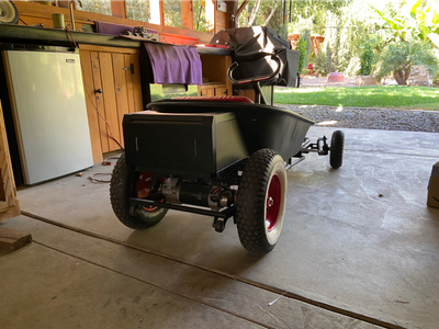
As noted in the introduction the frame is fabricated from a variety of parts and pieces that were laying around the garage. The rear portion of the frame is the hoop and side rails from a wheelbarrow. Photo 1 shows the frame from the rear. The red arrow indicates the hoop and side rails from the wheelbarrow. The blue arrow notes the joint where bicycle tubing was welded to the wheelbarrow section on each side. All the weld joints are reinforced with smaller diameter tubing slipped into the outer tubing which you see on the finished frame. Simple butt joints would be too weak even for this lightweight kart.
Photo 2 shows the front half of the frame fabrication. The red arrow notes the weld joint between the wheelbarrow frame in the rear and the bicycle tubing. The black arrow notes the bicycle tubing. The blue arrow notes the ninety degree curves from a steel a lawn chair and the green arrow notes another section of bicycle tubing. Photo 3 shows how the frame was further reinforced by adding additional bicycle tubing as a bottom rail (see red arrows). This configuration triangulates the frame structure and gives it its strength.
This is not necessarily how you would want to build a kart type frame if you have access to nice new steel. But if you like the idea of recycling and you don’t have a lot of handy cash, scavenged steel tubing from a variety of sources can be fabricated into an adequate but somewhat ugly frame. And for a rat rod type project, this technique fits the theme quite well.
Step 2: Front I Beam


Superstrut was used to mimic the look of an old fashioned dropped and drilled I beam front axle found on many early hot rods. Superstrut is a steel channel typically found in the electrical section of Home Depot or Lowes. It comes in 10' lengths and costs about $22. The Superstrut is cut at 22.5* angles and is clamped together for welding. (Photo I) Superstrut is galvanized so it should be sanded clean of the coating before welding to avoid any toxic fumes. The dropped axle is welded and then ground smooth. (Photo 2)
Step 3: Spindle Assemblies and Front Suspension


Spindle backing plates are positioned on each end of the axle to create 8 degrees of caster and 5 degrees of kingpin incline. The “angle finder” shown in the photo is hugely helpful for setting angles of all sorts. (Photo 1) Once in position the backing plates are welded to the I-beam axle. (Photo 2) The spindle mounts are fabricated from 1/4" flat stock. (Photos 3, 4 and 5) To create front suspension, the spindle will be attached to a “slider” which slides up an down the kingpin. The “slider" is made using two 12mm bore pillow block bearings and a cube cut from 1 ½" x 1/8" wall square tubing. (Photos 6 and 7) The slider is mocked up with the kingpin, which is a 12mm grade 8 bolt (Photo 8) and with the kingpin and spring. (Photo 9)
The spindle, a 5/8" grade 8 bolt, is welded to the slide cube at a 5 degree angle. This angle, coupled with the 5 degree kingpin angle, will keep the spindle horizontal to the ground. (Photo 10) The kingpin, spindle and spring can then be are assembled (Photos 11 and 12) . Note that the spring shown in the photo was later swapped out for 60 lb coil springs. (Photo 13) The final spindle assemblies are welded to the I-beam backing plates. (Photo 14)
Step 4: Steering


Steering arms are cut from 1/8" flat stock. (Photo 1) The arms are welded to the spindle cubes with their position determined by Ackerman principles. Basically this means the steering arms are on an imaginary line drawn from the center of the kingpin to the center of the REAR axle. If you are not familiar with Ackerman theory, there are many great web sites which explain it in great detail. (Photo 2)
The steering arms are connected to the steering column with adjustable steering rods. The steering rods are made using ½" conduit and 3/8" heim joints. The conduit has 6 evenly spaced notches cut in each end. (Photo 3). The notches are cut so that a 3/8" nut can be inserted in the end of the conduit and the flat sides of the nut line up with each notch. (Photo 4) A right threaded nut is welded into one end of the conduit using the slots as a guide and a left threaded nut is welded into the opposite end of the conduit in the same way. A left handed 3/8" heim joint is screwed in the left handed nut and a right handed 3/8" heim joint is screwed in the right handed nut. (Photo 5) The steering rod can be installed and is fully adjustable. Jam nuts are used to keep the rod secure once you have it adjusted to the correct length.
The steering column is made from conduit and the steering wheel is made by cutting and welding old bicycle handle bars into a semi-oval shape and that unit to a ½" bore sprocket hub. (Photo 6) The steering shaft itself is ½" threaded rod and a plate is bolted to the end of the steering shaft to connect to the left and right steering arms. (Photos 7 and 8)
Step 5: Mounting the Motor and Transaxle


In the original mobility scooter the motor is mated to a transaxle and sits in a “cradle”. (Photo 1) The motor and cradle are removed from the scooter and installed as a unit in the wheelbarrow kart. A suspension system is created by fabricating two pivot bearings. These pivots will connect the motor cradle to the frame while allowing it to rotate up and down.
The pivots are made from 1 ½ x 1 ½ square tubing and the hubs from two bicycle front wheels. (Photo 2) The center section of the bicycle hubs is cut away and the bearing cups are saved. (Photo 3) The bearing cups are welded into the open ends of the square tubing. (Photo 4) Our new pivots are considerable narrower than the original hub and there are not enough threads on the bicycle axles to use them for mounting. They are replaced with 5/16" bolts. But the original axles and nuts are 7mm and the original nuts must be retained because they serve as the outer cone which keeps the bearing in place. To make this all work, the bearing cones (the original hub nuts) are bored out to 5/16" so that they will slip over the new 5/16" pivot bolts. (Photo 5) A 5/16" nut can then be used to tighten the bearing cones in place and retain the bearing in the correct position. (Photo 6) A pivot is welded to each arm of the motor cradle. (Photo 7}
Dropouts are welded to the frame to mount the pivots. Note that the photo of the dropouts is with the frame flipped upside down. (Photos 8 and 9) The motor and cradle can then be bolted onto the frame. (Photo 10) Coil spring brackets are welded to the frame and the cradle and the springs are bolted in place. (Photo 11)
Step 6: Electrical System


The Makita batteries are mounted using Power Wheels adapters. These adapters are made to allow the use of various tool batteries in a child’s Power Wheels electric car and are available on Amazon or Ebay for nearly any brand of 18 or 20 volt battery. The battery snaps into the adapter just like it would snap onto a tool and most adapters come already wired. The adapters are screwed onto a 3" wide board and a fuse holder is wired into the system for safety. (Photo 1) The batteries can then be snapped into the adapters. (Photo 2) The battery board is then bolted to the underside of the pickup bed as shown by the red arrow in Photo 3.
The hand throttle from the original mobility scooter is mounted at the front of the wheelbarrow body so that it becomes a foot throttle. Press the right “paddle” and the car goes forward. Press the left “paddle” and the car goes in reverse. (Photo 4) An on/off switch is installed on the dashboard area of the wheelbarrow and a speed “governor” is also mounted on the dash (See red arrows Photo 5) The governor is a potentiometer which sets the maximum voltage to the motor when using the throttle. It can be adjusted from 1 to 10 so that the top speed of the kart can be limited for smaller children.
Step 7: Seat and Upholstery

The seat is made with two pieces of 1/2 inch plywood hinged at the back and bolted to the floor pan. The boards are covered with 1" foam and then upholstered with outdoor, UV resistant fabric. (Photo 1) The interior of the wheelbarrow is covered in 1" rubberized foam which can be seen if you look closely at the interior photo. This foam was originally shipping protection/packing for a large item I had received. The foam is held in place with contact cement and adds a bit of protection for the driver.
Step 8: Grill Shell


The shape of an early 30's hot rod grill shell is fairly unique and difficult to replicate. But rummaging through my shop I found an old Rubbermaid mail box that looked like it could fit the part. I sliced off the front 2" of the mailbox. (Photo 1) I trimmed off some of the extraneous material, put on a coat of flat black paint and bolted it to the frame. (Photo 2 and 3)
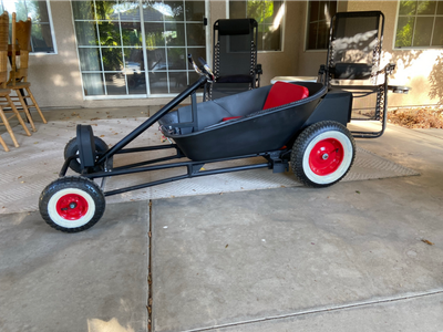
Step 9: The Finished Mini Hot Rod