

Introduction: Homemade DIY Fly Cutter, Double Edged, for Milling Machine.


Fly cutters are a frequently used tool on a milling machine. They usually comprise of a single cutting tool mounted at a relatively large radius and are used for facing surfaces. Compared to many fly cutters I prefer them to have a lot of inertia to smooth the cutting action as well as reducing the tendency to chatter. I also like to have 2 or more cutting edges. This instructable shows how I made mine and will show why I like 2 cutting tools.
The main photo above shows my fly cutter and the side photos show a couple of typical commercial variants.
Step 1: Materials and Tools


Materials
- A flanged R8 chuck mounting, pictured above left. You will need to have a chuck mounting plate to suit your own milling machine. I have a Bridgeport with the R8. Other common possibilities would be morse taper, CAT30 or CAT40. Actually I bought the whole chuck assembly, as shown right, and I use the chuck on a rotary table and the mounting plate for the fly cutter. Here is a link to the one that I got, but you should be able to find the mounting plate only on the net. 4-3-Jaw-Self-Centering-Lathe-Chuck-w-Cert-003-TIR-R8-Shank
- A piece of steel or cast iron of a size to suit the fly cutter that you want to make. I had an old chuck mounting plate which I used. I have seen examples made from car engine flywheels
- Two (or more) pieces of 0.25" HSS or carbide rods for the cutting edges.
- Some grub screws and mounting bolts.
Tools
- Milling machine. You need this to use the cutter but probably not to make it.
- Lathe.
- Drill press or you could use the milling machine to drill holes.
- Thread taps to suit the grub screws and mounting bolts.
Step 2: Combining the Two Main Pieces


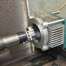
I needed a substantial mounting method for the heavy rotor containing the cutting tools. An R8 to 100mm chuck flange was ideal, buying this in saved me a lot of work.
This has a 72 mm diameter spigot for location and three holes for M8 mounting bolts. The rotor was made from an old chuck plate which gives plenty of the inertia which I regard as important for fly cutters. It was faced off, drilled and tapped for mounting and a register bored to suit the spigot on the mounting plate. Two opposing holes were drilled to take 0.25" tool blanks, holes were drilled and tapped M6 at 90 deg. to take grub screws to hold the tools. This allows me easy depth of cut adjustment, and the circular tools allow rotational adjustment to change the rake angle for different work piece material. I have a choice of grinding tools from HSS blanks or more usually I grind the tools from old 0.25" carbide milling cutters.
The outer diameter is 190 mm. Note that there are some additional holes in the rotor, they are a legacy of its previous life and have no purpose in this tool. The only necessary holes are the 3 for mounting the R8 flange, these holes are tapped 8 mm, in addition there are 2 1/4" holes drilled for the tool bits and another 2 drilled and tapped for the tool holding grub screws which I made 6 mm.
Step 3: Balancing

I like things to run a smoothly as possible and I usually balance rotating items where possible. This is more important with cast iron rotors than steel because cast iron is generally not as homogenious as wrought material.
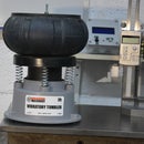
In this case I used a static balancing rig that I made for balancing and aligning single cylinder motorcycle crankshafts but there are many other balancing methods that could be used. I will probably make another instructable on my balancing rig in the future.
To be honest, because of the large radius of the cutting edges, the working RPMs are not high to maintain ideal cutting speeds and balancing is generally not really necessary if the tool is made accurately. I am a bit of a perfectionist with such things and I had a balancing device handy, so it was easy for me to do.
Step 4: Why Two Tool Bits?


Now we come to the reason for the two cutting tools.
One cutting edge is set at a slightly greater radius than the other. The tool at the larger radius will hit the work first on each revolution followed by the second tool. I set the first tool at a height suitable for a roughing cut and the second tool gets set an amount lower to act as a finishing cut. In effect this gives me two passes in one. Each tool can be ground differently to suit the different needs of roughing and finishing.
Alternatively, both tools could be set such that each removes a similar depth of material, this allows the fly cutter to take double the material in a single pass as compared to a single tool cutter.
Of course, there is plenty of room to add a bunch more cutting bits around the rim of a large diameter rotor which for a given chip load (ask Mr. Google if you are unfamiliar with the term "chip load") would allow higher feeds and quicker metal removal. However, more tool bits makes the setup of cutting depth more difficult and time consuming. Personally I think that 2 or 3 is optimum for a general purpose fly cutter. If you mainly use the tool on a specific repeat machining job then there is a case to argue for more tool bits.
Step 5: Setting the Cutting Tools.


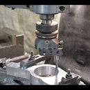
The left photo shows the deepest cutting tool being set onto the work piece as a zero reference. This is the tool bit on the smallest radius and hence is the tool bit which gives the final cut.
Next, the rotor is turned 180 deg. and the other tool bit's height is set onto a feeler gauge of the desired thickness. This will be the first cutter to attack the work piece and would normally be set for a roughing cut. The difference between the depth of the two machined surfaces will be equal to the feeler thickness.
Using a feeler gauge as described is the most universal and accessible method of setting the two tools at different depths. It can be done equally well on a pure manual mill, one with a DRO or even a CNC machine. However, there are several other methods and those with the facilities will want to use one of the available tool height setters commonly used on CNC machines
Step 6: Conclusion and the Movie
I have shown the benefits to be obtained by the simple addition of a second or more cutting edges to a fly cutter, preferably one with large inertia.
I suggest watching the video to the end to see the setting procedure fully and to see the actual cutting action.
If you found this post useful please like, share and follow/subscribe to both my instructables and Youtube channels.
Thanks for watching.


