

Introduction: Getting Started With Relays


This instructable will make you familiar with Relay and its working using a simple circuit.
Step 1: What Is a Relay?


A relay is an electrically operated switch. It is mainly used to control higher voltage circuits with lower voltage. The 'control' and 'controlled' circuits are electrically isolated from each other.
Since relays are switches, the terminology applied to switches is also applied to relays; a relay switches one or more poles, each of whose contacts can be thrown by energizing the coil.
1) Normally-Open(NO) : The circuit is disconnected i.e. open when the relay is inactive.
2) Normally-Closed(NC) : The circuit is connected i.e. closed when the relay is inactive.
Step 2: Things You Need
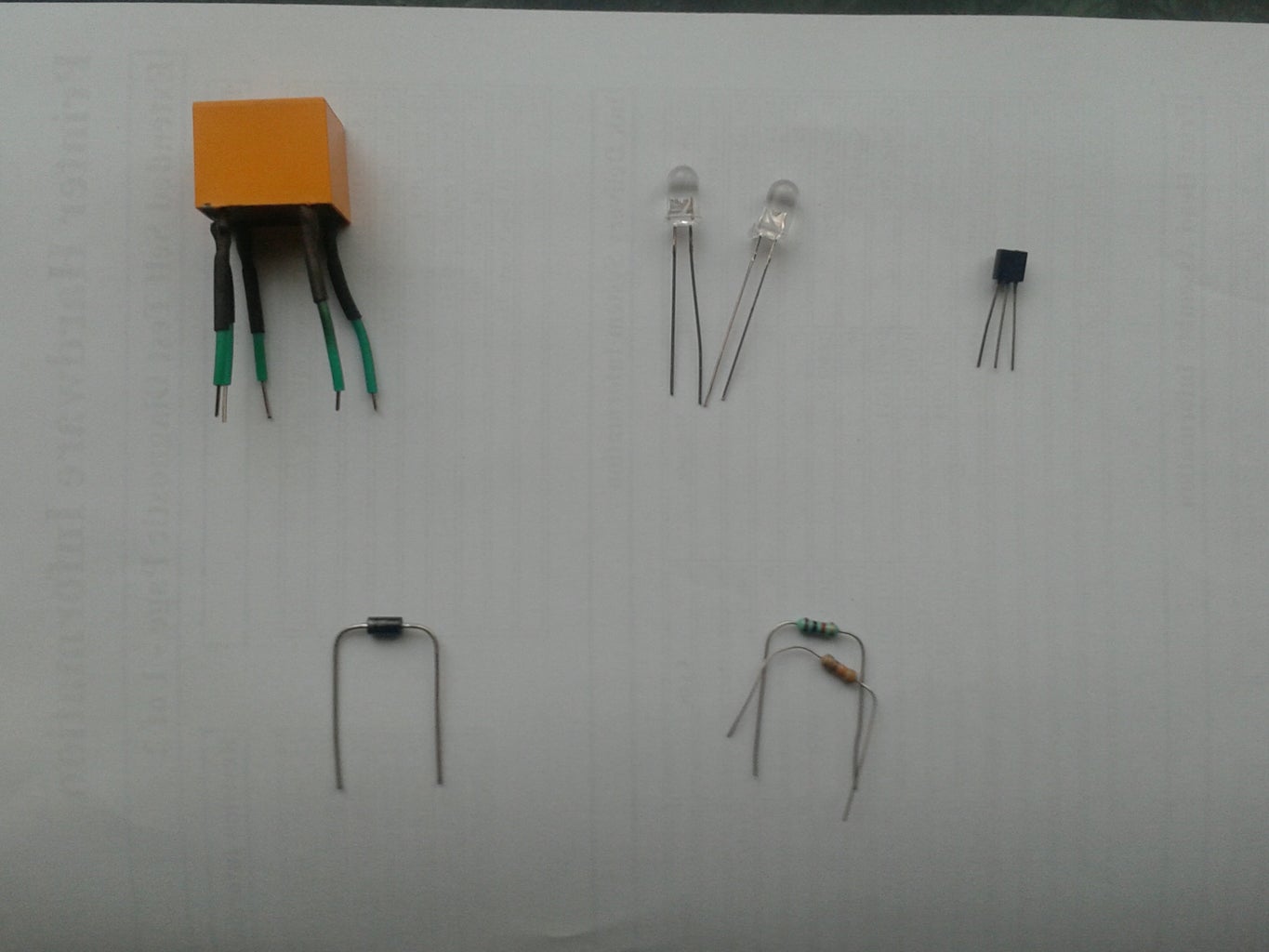
Things needed to make a simple relay circuit:-
1) Two LEDs (in this case, white) to demonstrate NO and NC.
2) NPN Transistor
3) Diode (Any value will do)
4) Resistors:- 1k for transistor base and 220 ohm for LEDs. The value depends on LED colour.
Few other things are:-
1) breadboard
2) wires
Step 3: Circuit Diagram

Most of the relays work on 12V DC power supply. Here, a transistor controls the 12V supply which goes to the Relay.
As mentioned before, there is no actual need for transistor if you want to simply control the output by manually turning the 12V supply ON or OFF.
The transistor comes into picture if you want to control the circuit automatically using microcontrollers (like Arduino). To do so, just replace the 5V power supply with "output" of microcontroller.
NOTE:- Make sure that you connect the GND of both the power supplies together.
The diode is used to avoid any damage to the transistor.
NOTE: Add a switch between the base and 5V power supply.
Step 4: Identify NC, NO & C
Most of the relays have the abbreviations (NO, NC, C) printed near the leads. If its not, follow these simple steps to identify them:-
1) C (common) can be easily recognised as it is placed in the middle of any one of the side of a relay.
2) Coil terminal lies besides the Common terminal.
3) Once you have figured out which one is common then NC and NO can be identified using continuity tester from multimeter.
Connect one probe of multimeter to common(C) and other to any one of the two leads on the opposite side. The one which gives continuity is Normally Closed(NC) and so the other is obviously Normally Open(NO).
NOTE:- Make sure that the relay is not connected to 12V supply i.e. inactive
Step 5: Connections


Please note that Arduino is only used as a 5V power supply.
Make sure you follow these important steps:-
-The GND of both the power supplies are connected together.
-The diode is connected properly with correct polarity to avoid damage to transistor. (I burnt a transistor because of neglecting the polarity :P )
-Connect the base of the transistor to +5V via 1K resistor and a switch, Emitter to GND and Collector to one of the Coil terminals
- +12V is connected directly to other coil terminal and not on the breadboard power rails.
Step 6: Working


In the first picture, the switch is open and so the relay is inactive. And so the LED connected to NC is light up.
In the second picture when the switch is closed, the relay gets activated thereby pulling a switch inside it which then gets connected to NO.
The LED at NC turns OFF while the LED at NO turns ON.
Step 7: Some Other Ideas!
-Control relay using Arduino or any other microcontroller.
-Control high voltage electrical appliances. (Make sure that you don't exceed the current limit.)
-Home automation using relay boards to power up lights, fans and much more.
Thank you for reading this instructable. Hope you have enjoyed it and learnt the basics of relay.
If there is any mistake in the instructable, let us know in the "Comments" section below with your relay project and many more awesome ideas. Those will be updated in our instructable.


