

Introduction: Gongbot: Networked Robotic Gong


At the Stripe office, there's a tradition of ringing a gong at meal times. Several months after I started, we outgrew our space and had to split up across multiple floors. Instead of giving up on the gong, I built a cluster of networked robotic gongs! Pressing the button on any Gongbot (or the gongbutton) triggers all of the Gongbots in the same cluster and a message in an IRC chatroom.
Gongbot is based on the Spark Core, connects over WiFi and communicates via an MQTT message broker. It uses a strong servo to swing the beater into the gong. At the time of this writing, we have 3 gongs and a button operating in the office and more on the way.
Step 1: Parts, Tools and Software
Parts
- Gong, stand and beater: Zildjian P0565
- 3D printed enclosure: You can order one on Shapeways or print one yourself from the model there (you'll need a very good 3D printer, I use some small features).
- Spark Core: Spark has since released a cheaper/better version called the Photon but the code won't be immediately compatible.
- Momentary pushbutton: The enclosure is based on this button from Radioshack but you can probably find something that fits the same opening.
- Servo: Solar Servo D771
- N-channel MOSFET: I used the surface-mount NTR4501 but if you value your time and eyesight, get a throughole part instead (e.g. a NTD4906N). You could probably also use an NPN transistor that can handle up to 1A.
- 4x6-32 nuts and machine screws: Used for mounting the servo in the enclosure.
- 2x10-24 nuts and machine screws: Used for mounting the enclosure to the gong.
- USB power adapter / wall charger: Look for something rated to 1A.
- Nails: Very fine nails for attaching the beater to the servo.
Tools
- Drill: Bits for a #10 clearance hole and a tiny bit for your nails (I used a #60 bit with a special collet).
- Soldering iron and solder
- Dremel
- Various basic handtools
Software
- Spark command line client: https://github.com/spark/spark-cli
- dfu-util: I installed it via Homebrew on OS X.
- Gongbot firmware: See the attached bin file or look on github.
- Serial terminal: minicom, screen or Putty should all work though I found minicom easiest to work with.
- Note that you may choose to build the firmware from source to get the latest version. You should be able to find instructions for setting up a build environment in the Spark documentation. You can find the source and its dependencies at these links:
Attachments

Step 2: Electronics


Prepare the servo
The wires on the servo stick out in a way that prevents it from fitting in the enclosure.
Snip off the connector at the end of the servo cable. Unscrew the 4 screws on the back of the servo and remove the backplate. Be careful not to disturb the innards in the process. Slid the rubber stress relief shoe off the end of the cable. Using your Dremel, grind a notch on the back plate of the servo such that the wire can stick straight out the back. Reassemble the servo.
Prepare the Spark Core
Out of the box, the Spark Core comes with header pins that are great for prototyping but won't fit in the enclosure. Remove the black plastic spacer at the base of each set of pins then carefully desolder and remove each of the 24 pins from the Core. I found this to be a slow process with a soldering iron and needle nose pliers.
Connect the electronics
Break out your soldering iron and connect things up as follows:
- Button pin 1 - Spark GND
- Button pin 2 - Spark D4
- MOSFET Gate - Spark D7
- MOSFET Source - GND
- MOSFET Drain - Servo Brown
- Spark Vin - Servo Red
- Spark A7 - Servo Yellow
The wires on the button need not be very long -- just a bit longer than necessary to fit in the enclosure. It's helpful to have a bit of slack on the servo wires so you can get the Core positioned within the enclosure. They can't be too long or there won't be enough space for them to sit behind the mounted servo. Be especially careful with how you position the MOSFET as there isn't a lot of room for it in the case.
Step 3: Flash, Configure and Test
Flash the firmware
Follow Spark's directions for setting up the command line client.
Connect the Spark Core to your computer via USB. The LED should come on and then nothing should happen.
Hold down both buttons on the Core. Release the RST button. When the LED starts flashing yellow, release the MODE button. Run "spark flash --usb core-firmware.bin" from the command line. You should see a series of text and then progress dots while the flashing is in progress. You may get a poll timeout error message at the end of the process -- that's a known Spark bug but not a problem.
Configure the core
Run "spark serial list" to find the serial port or device file associated with your core. On OS X, mine was "/dev/cu.usbmodem1411". Connect to your core using your serial terminal. With minicom I use the command "minicom -D /dev/cu.usbmodem1411".
Press RST. A 2-3 seconds after resetting, press Enter in your serial terminal to start device configuration. You'll be asked for the following:
- App type: Enter "0" for gong.
- MQTT Host: The hostname of an MQTT broker (e.g. m2m.eclipse.org)
- MQTT Port: The port of the MQTT broker (e.g. 1883)
- Root topic: An MQTT topic that your Gongbot will publish on and subscribe to (e.g. /instructables/gongbot). Gongbots that share the same root topic will ring together. It must start with a trailing slash and cannot end with one.
- Name: A unique name for your Gongbot. This name can be used by other software you have listening such as an IRC bot.
At this point, the serial port will reset and the Gong will enter WiFi config mode. Press "w" to write a new WiFi configuration and follow the prompts. If you've already configured the WiFi, you can press RST to skip this step.
- SSID: Name of your WiFi network
- Security: Note that Spark indicates they've had problems with WEP networks.
- Password: Password used to connect to your network.
Test
The LED on the Core should eventually start pulsing cyan indicating that it is online. Aside from the use of cyan to indicate a connection with the MQTT broker, the other colors should match the Spark documentation. Each time the Core boots up, the LED will transition through the following colors:
- White: Starting up
- Blue: Searching for WiFi
- Green: Connected to WiFi
- Cyan: Connected to the MQTT broker.
With the LED pulsing cyan, press the button. The servo should move a few times over a few seconds. If not, check your wiring and look in the serial terminal log for clues.
Step 4: Final Assembly


Install the electronics
Insert the Core into the bottom of the enclosure, pushing the USB connector through the hole at the back. The USB-side of the Core PCB should be flush with the enclosure wall. Press firmly on the antenna-side of the Core PCB to secure it in place. It should be quite snug but you shouldn't have to force it.
Remove the nut from the button and thread the button through the hole in the front of the enclosure. Hold the button in place from the inside with a pair of needle-nose pliers and tighten the nut from the outside.
Slide 6-32 nuts into each of the 4 slots just inside the main opening of the enclosure. Insert the servo into the enclosure and secure it into place with 6-32 machine screws.
At this point it's probably worth powering up the Gongbot again to make sure you did everything correctly. The servo should move when you press the button and you should be able to faintly see the Core's LED through the plastic on the side of the enclosure.
Attach the gong
Drill two 10-24 clearance holes at the center of the top rail of the gong stand. It may be helpful to use the enclosure to mark off the position of the holes. Attach the Gongbot to the stand with 10-24 machine screws and nuts.
Attach the beater
Find the straight, two-sided servo horn that came with your servo. Drill two tiny pilot holes towards the far end of the beater. The holes should be smaller than your tiny nails and spaced to align with the farthest apart holes in the servo horn. Feed the nails through the servo horn and hammer them most of the way into the beater. Bend the remainder of the nails around the servo horn to secure it in place. I also used some hot glue to help hold things together.
Admittedly this is one of the least elegant parts of this design. It would be hard to do without a tiny #60 drill bit and some very small nails. Feel free to improvise!
Power up the gong, press the button and wait for the movement to stop. Press the servo horn onto the servo such that the beater is pointing straight down. This is the neutral position that the beater will return to after each swing.
You're done -- give it a hit!
Step 5: Advanced Gonging

There's not much point in having a networked Gongbot if it isn't going to talk to anything. I'd suggest:
- More Gongbots!
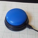
- A big button to trigger your Gongbots.
- An IRC client to announce gongs.
- Your own custom client. Gongbot will publish a "released" message on an MQTT topic like "/root/topic/name/button" when the button is pressed and released. You can subscribe to these topics from your own apps or even write apps to trigger the gongs.
Happy gongs!

Participated in the
Formlabs Contest


