

Introduction: HOW TO READ CIRCUIT DIAGRAMS


this instructable will show you exactly how to read all those confusing circuit diagrams and then how to assemble the circuits on a breadboard!
for all the electronics hobbyist wannabes this is a MUST-READ instructable.
knowing how to read circuits is a very useful skill that will help you out all the time. especially if you start messing around with building little electronics projects.
In addition to reading this instructable it may be a good idea for you to read my other instructable "electronics components and what they do" to get a good understanding of what you are doing when building a project. (woops not done with this yet, i got caught up with other stuff, check back in a week or so)
Step 1: So What Are All Those Symbols???


here is a little guide that shows you the basic symbols for all sorts of components. its handy to keep a little guide like this around in case you forgot some. Plus, while you're beginning you might have to refer to it pretty frequently. I have boxed the most common symbols in red, these are the ones you should get to know by heart. the others you can always refer back to the guide for.
dont be overwhelmed its simpler than you think, just stay with me
Step 2: Okay, But How Is Each Part Connected?


physically parts are connected by wires, in the diagrams you will see black lines going from one part to the next. this means that you connect them with a wire
when the black lines cross in a diagram there are ways of telling whether or not the wires should be connected to each other as shown below.
Step 3: HOLD UP: What About Polarity?


some components to a circuit board are polarized, meaning one side is positive and the other is negative. this means you have to attach it in a certain way. for most symbols polarity is included in the symbol. in the the photos below you will find a guide to distinguishing polarity for various symbols. to find out the polarity of the physical part a general rule of thumb is to look for which metal lead wire on the part is longer. this is the + side.
Step 4: YOUR FIRST SCHEMATIC!!!

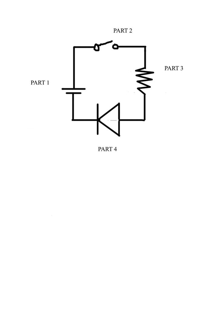
Okay, so now that we've gone through the basics, lets try to read a real world schematic of a circuit. so lets dissect this circuit!
*I have numbered each symbol so that we stay on the same page while im describing each part
the first symbol you see is the one with two horizontal lines, one smaller than the other. do you remember what this is? you can always look back at the guide. its a battery. in this case a nine volt battery. if you look back at the polarity chapter you will see that the longer line represents the positive terminal of the battery.
next you can see that there is a line connecting the positive side of the battery to the second part which if you look back at the guide you will find is a switch with two positions: closed (on), and open (off). seems backwards? its not because if you think of that little door like thing on the symbol closing than it would complete the circuit, thus being "on".
so when we flick the switch closed where does the electricity go next? that squiggly line is a resistor. this is a symbol you REALLY want to memorize. they are in almost every circuit. basically in just makes sure that the not too much power from the battery is sucked up by the next part by resisting the flow of electricity.
so the final part is the triangle thing. that is a diode (as you can see on that handy chart in this ible). in this case a light emitting diode, or LED. remember LEDs are polarized so when you actually go to make this circuit make sure you put it in right.
finally you can see that the negative side of the LED connects back to the negative battery terminal and the circuit is complete!
THERE IT IS! a flash light! you can now continue on to building the actual thing!
building this circuit will bring its own challenges. so, if you want to be walked through check out my instructable: "making circuits: the beauty of breadboards". it will go through the exact steps of building this flashlight, including where to buy parts for cheapest. but also teach you more important knowledge for building all sorts of circuits. (i did actually make this one)
important note, the schematic will not tell you all you need to know. in most there will be text seperate telling you exactly what parts to buy, you cant just throw in any resistor or any capacitor and whatnot. i have the details for the parts in this project in the next instructable mentioned above.
PLEASE RATE AND COMMENT
this is my first ible, i need feedback


