

Introduction: Heartbeat Sensor #phablabs


Building a heartbeat detector with infrared. Taking your pulse is as simple as holding your finger to your neck and count the beats with your watch. But if you turn that mechanical pulsing action into an electric signal, you are able to record the data. The heartbeat detector uses the amount of infrared light reflected by the blood circulation inside your finger to generate that signal.
Properties of this workshop:
Timeplanning: Total: 1,5h
1. Introduction: 15 minutes
2. Soldering: 60 minutes
3. Assembling the case: 5 minutes
4. Uploading the code: 5 minutes
5. Cleanup: 5 minutes
Target audience: Young professionals (18+ years old)
Estimated cost: € 20
DISCLAIMER: By using this information you agree to be legally bound by these terms, which shall take effect immediately on your first use of the information. PHABLABS 4.0 consortium and its member organizations give no warranty that the provided information is accurate, up-to-date or complete. You are responsible for independently verifying the information. VUB cannot be held liable for any loss or damage that may arise directly or indirectly from the use of or reliance on the information and/or products provided. PHABLABS 4.0 consortium and its member organizations disclaim all responsibility to the maximum extent possible under applicable laws: All express or implied warranties in relation to the information and your use of it are excluded. All liability, including for negligence, to you arising directly or indirectly in connection with the information or from your use of it is excluded. This instruction is published under the Creative Commons licence CC-BY-NC.
Step 1: How Does This Heartbeat Sensor Work?
When light goes through a finger, it encounters blood vessels. Part of the blood scatters and absorbs the light. When the heart beats, the flow of blood changes and therefore also the amount of light transmitted through the finger. Measuring the variation of light transmitted and converting this in an electric signal enables us to draw the heart beat signal as seen on screen at the hospital. Finding and counting the larger peaks will give us the heart rate and by attaching a sound to each of these peaks, we obtain the famous “beep” signaling that our heat is pumping.
The light used here has a wavelength in the Infrared region (IR), simply because the flesh (muscle) is absorbing most of the visible light and let pass the Infrared. The blood reflects more the IR and therefore we are more sensitive to the blood flow changes.
Step 2: Part List

Photo 1: Overview of all parts needed.
Photonics parts:
*Plexiglass pannel to lasercut the front panel, back panel and spacers (file attached: heartbeat sensor ontwerp v3)
*1 LCD (liquid crystal display)
* 4 LEDs
* IR LED
* Photodiode
Other parts:
*4 M3x30mm screws + 4 M3 nuts
*16 pinheaders
*1 PCB (gerber files attached)
*1 Arduino Nano + USB mini B cable
*5 resistors 4K7
*Opamp
*Piezo buzzer
*momentary switch
*2K pot
*Resistors: 1x 120R, 1x 330R, 1x8K2, 1x 1K5, 1x 1K, 1x 18K, 1x 560K, 1x 1M8, 1x 2K2
*capacitors: 1x 1 micro-Farad, 1x 100 nF, 1x 33 nF, 1x 10nF
Tools (for example in Fab Labs):
*lasercutter
*Soldering iron
*Flush cutter/wire cutter
*A computer to program the Arduino on the board
Don't find the material you are looking for? Via this link you could buy all the photonics material needed for this workshop. http://b-photonics.eu/photonics-toolkit/general-p...

Step 3: Assembling of the Heartbeat Sensor


Before you start assembling, make sure you have all the parts. You can check with the picture above. Next, we will be soldering all the components to the printed circuit board (PCB).
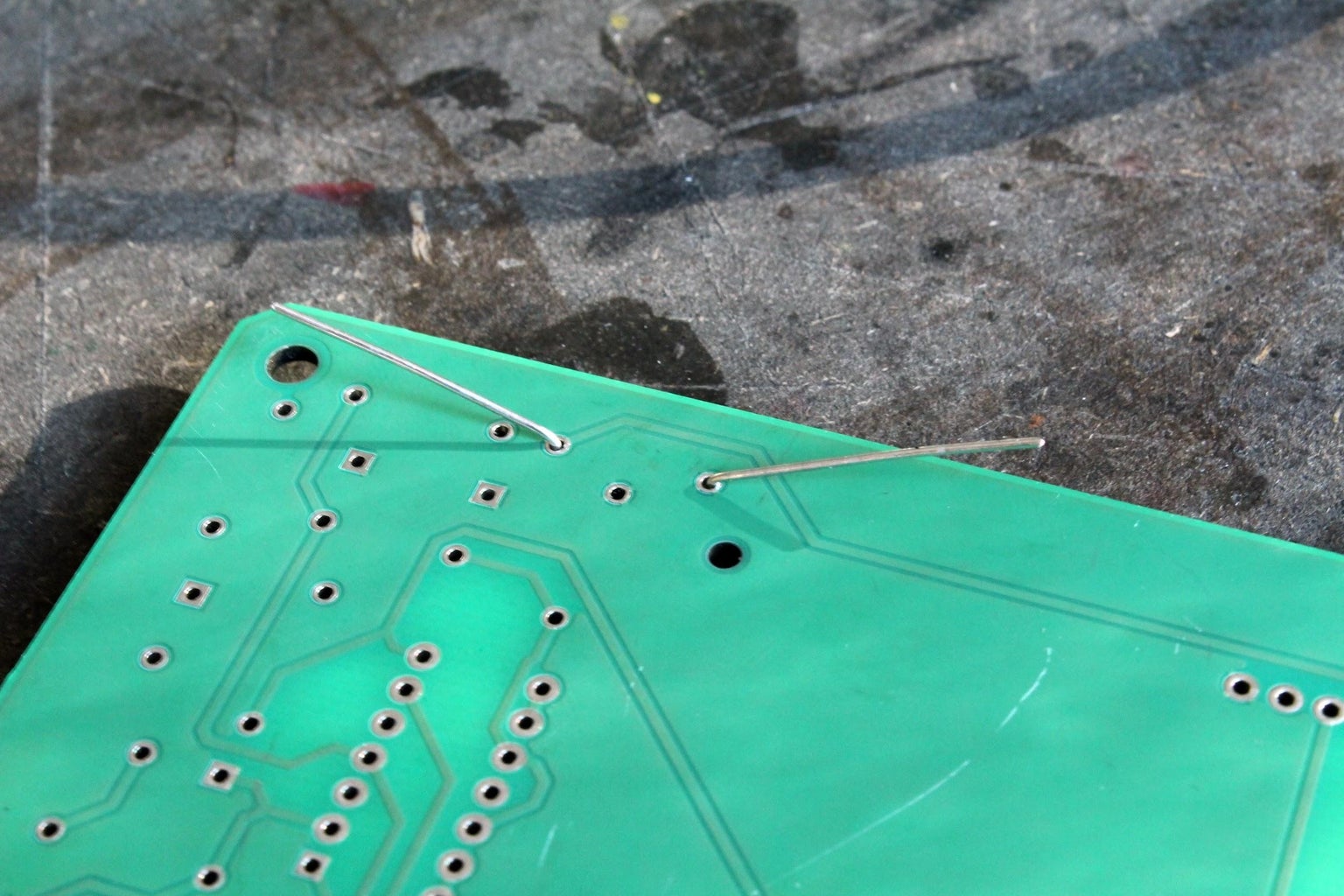
To solder a component, first bend its leads like so if they are not already aligned. See Photo 1
Photo 2: Then, place it in the holes that have the value of the component printed. For these resistors: check the colour codes carefully to make sure it is the right one.
Photo 3: To make your life a lot easier, you can bend the leads over. This makes the component stay in place while soldering.
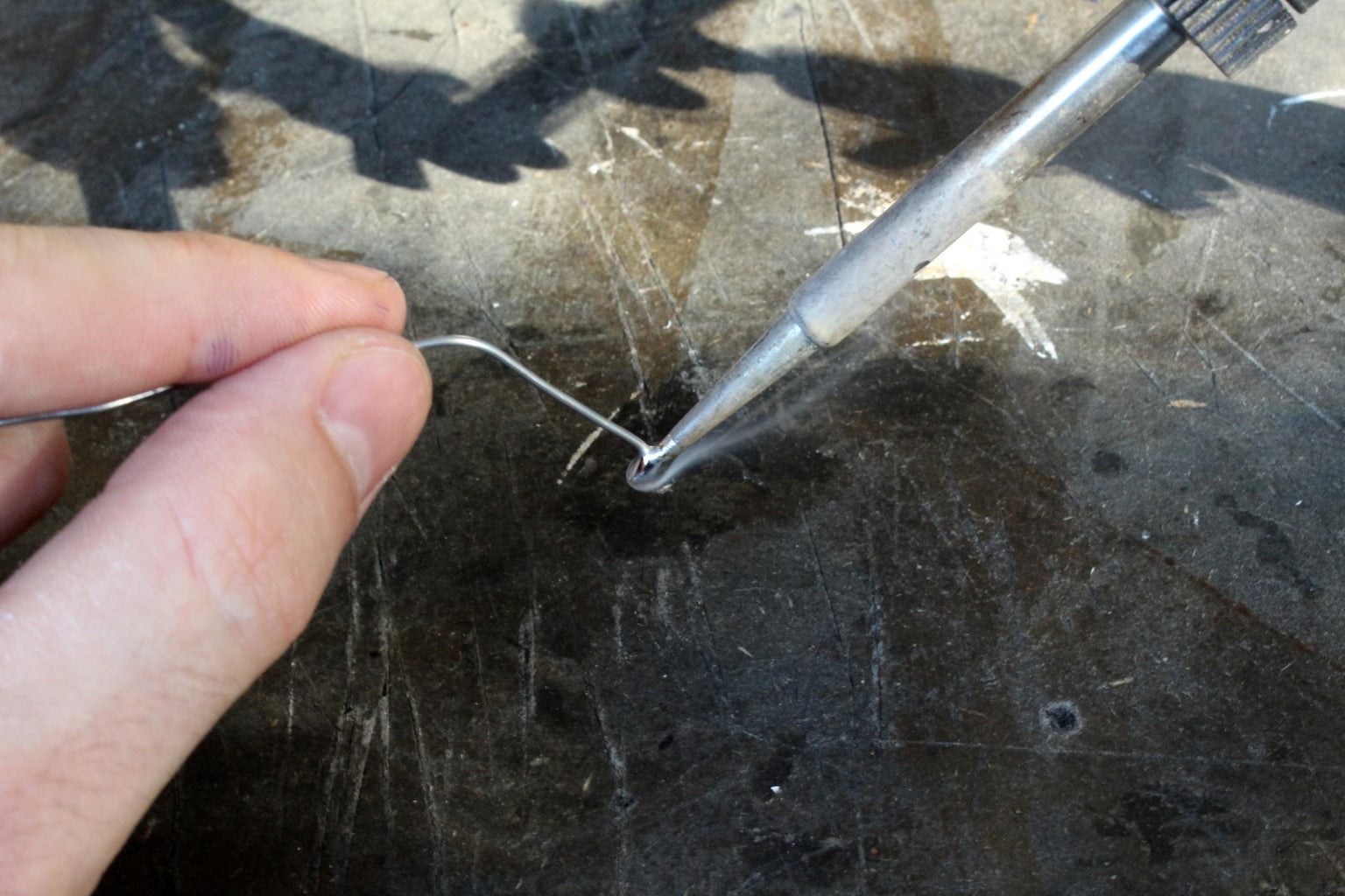
Photo 4: Now, heat up the soldering iron. Apply some solder to the iron (‘wetting’). This will ensure the component is heated well.
Photo 5: Hold the soldering iron to the lead and the PCB so they heat up. Then, apply solder to the components (not the iron).
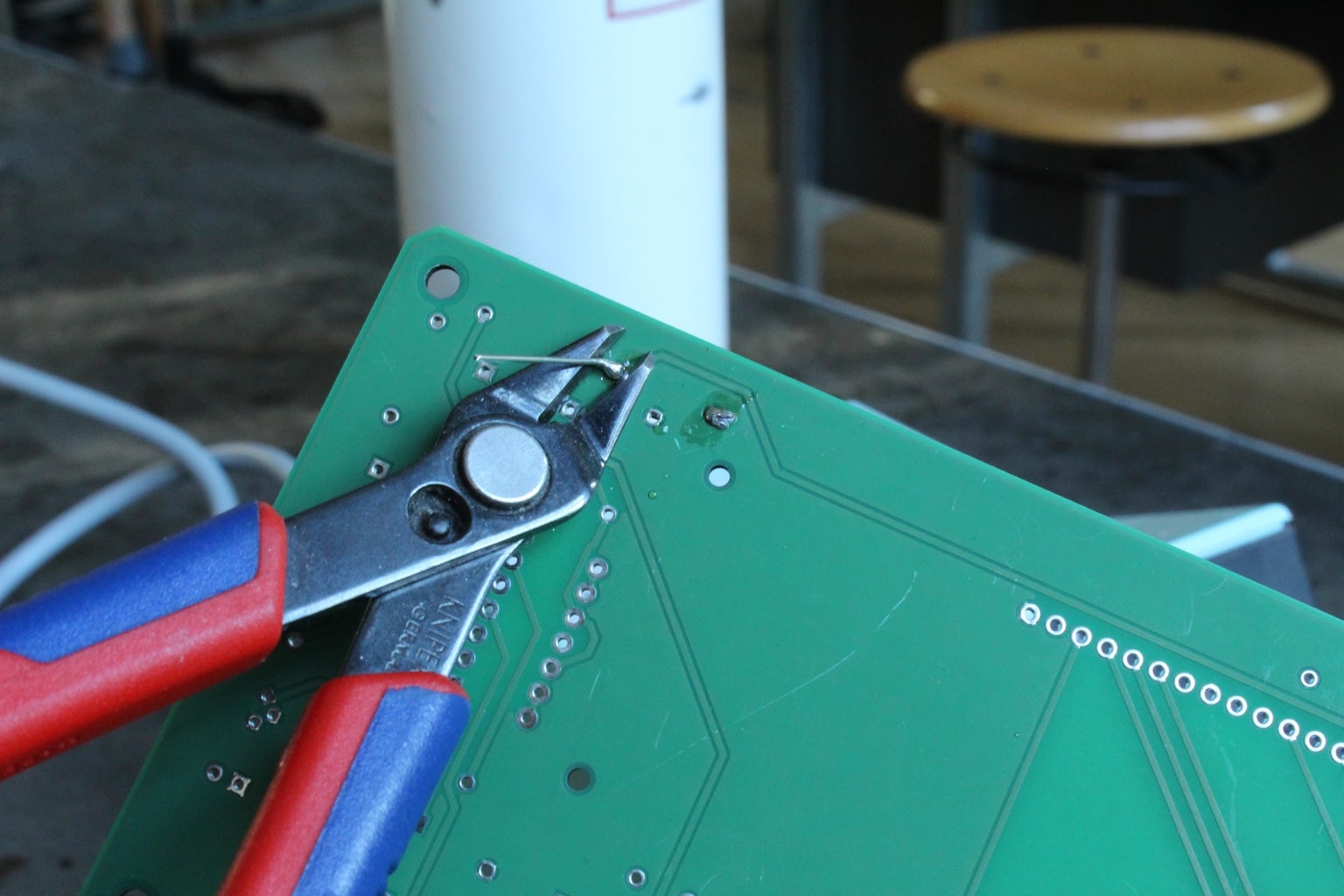
Photo 6: Then, trim the leads.
Solder the other components using these steps. Pay attention to a few components though, they have a specific orientation they need to be placed in.
The opamp chip has a notch that is also marked on the PCB. Photo 7
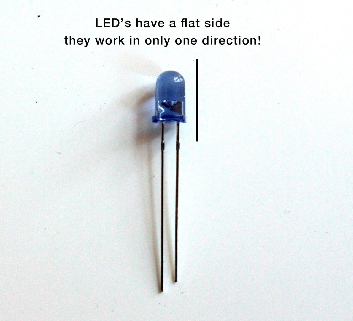
Photo 8: LED’s have a flat side that is also marked on the PCB.
When all components are soldered, the board should look like photo 9.
Now, the case can be fitted. Use the spacers to set the front panel at the right height. Photo 10
EXTENSION
The Heartbeat sensor was built to be hackable! Feel free to take out components, swap them around or add cables to make a remote sensor. Maybe the LED’s should be a different colour… Experiment! The row of breakout holes on the PCB can be used to access unused input and output pins of the Arduino Nano.
Photo 11: schematics of the heartbeat sensor.
Step 4: Program the Arduino


To make the sensor work, we need to install some software on the Arduino. This is done through the Arduino IDE. Photo 1
Get the Arduino IDE at https://www.arduino.cc/en/Main/Software.
Copy the LCD library folder in Documents/Arduino/libraries (see drive).
Now, download the code for this workshop from the @sciencecentredelft Github (or from the PHABLABS Drive):
https://github.com/sciencecentredelft/Heart-beat-sensor and tinyurl.com/phablabsheartbeat also links to this page. Photo 2
Photo 3: Open the code in the Arduino IDE. Then, go to Tools > Board and select ‘Arduino Nano’.
Photo 4: Then plug the Heartbeat sensor in your computer and go to Tools > Port and select the newly available option (either COMxxx on Windows or /dev/xxxxxx on Mac).
Click the arrow to upload the code to the Arduino on the PCB.
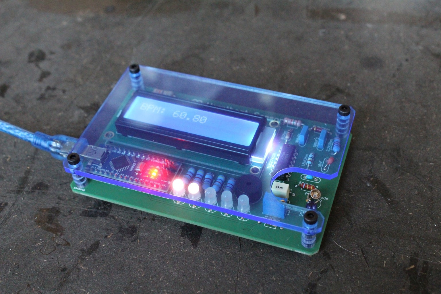
Photo 5: Your sensor should be done! The screen will show you your heart rate in beats per minute (BPM).
EXTENSION
The Hearbeat sensor was built to be hackable! The signal that the Arduino reads can be seen in the Serial plotter (Tools > Serial plotter). Can you figure out what the code does by looking at the two lines? Do other people’s heartbeats look different? What else could you do with this signal? Could you detect other things than heart rate?
Photo 6
If you want to learn more about programming Arduino’s, have a look at the Arduino Reference page: https://www.arduino.cc/reference/en/.
Step 5: Conclusions


What we learned?
You learned how optics can be used in sensors, how electronics can make the information useful. You also learned to solder well, a great skill for hacking electronics.
Concluding thoughts
A lot of medical devices use photonic principles: X-ray imaging, ……
What other photonic principles can we use in medicine? Are there any already in use in biology?
ABOUT PHABLABS 4.0 EUROPEAN PROJECT
PHABLABS 4.0 is a European project where two major trends are combined into one powerful and ambitious innovation pathway for digitization of European industry: On the one hand the growing awareness of photonics as an important innovation driver and a key enabling technology towards a better society, and on the other hand the exploding network of vibrant Fab Labs where next-generation practical skills-based learning using KETs is core but where photonics is currently lacking. www.PHABLABS.eu
This workshop was set up by the TUD in close collaboration with ScienceCenterDelft.


