

Introduction: Hit Point Tracker


In this age of Virtual Table Top gaming and pdf character sheets. I found myself longing for something tangible that would save me from swapping tabs and give me something to hold on to. Having seen some hit point trackers around the internet I decided I wanted to make one of my own. So if you want to make your own, understand how to customize it, or just want to get a glimmer into how my mind works come along with me on this hit point tracking adventure.
As a side note if you like the Corgi or Labrador Steel Defender Mini's in the photo. I designed them myself and their .stl files can be downloaded for free.
Step 1: Software, Tools, and Materials
Software
- Autodesk Fusion 360
- Inkscape(or other vector graphics program)
- Lightburn(or whatever laser control software your laser uses)
Tools
- Paint brushes
- Laser Cutter
- A small file
Materials
- 3mm Birch Plywood
- Painters tape
- Wood dye (I used two colors of this dye - this is not an affiliate link.)
- Clear Polyacrylic -satin finish
- Nitrile Gloves
- Paper towels
- Optional Super Glue
Step 2: Dream, Devise, Flounder, and Revise


I've seen some hit point tracker floating around on the internet for sale and felt inspired to make my own. If you want to follow through my design process and see how I made the vector file for cutting read on if you just want to get to lasering download the .svg from the next step and then you can skip to the laser cutting step.
Since you are still here and reading I'll start with my design goals. I find it helpful to make a list of what I want a thing or project to do before setting about figuring out how to design it.
Design Goals
- Small enough to not be a hassle to have out on my desktop
- Ideally the numbers would click into place. (So I wouldn't have to worry about loosing a number if my cats knocked it off my desk)
- Look neat.
- Be made from 1/8 inch (3mm) birch plywood(because that was the stock I had on hand)
With these design goals in mind I fired up Fusion 360 and got to work. (I'm no expert on Fusion and so as we step though how I designed this object keep in mind I might not be doing things in the most efficient way possible but it is the workflow I've developed by watching how to videos and self teaching.)
Since the whole design was going to be centered around two number wheels I started with them. Based on the design points I had laid out I knew I would need an inner void and some form of notches to click my numbers into place. I also knew that my two digit wheels would need 10 spaces for the numbers 0 thru 9 so I could count as high as 99 and as low as 0 (Hopefully not down to 0 too often.) So I made two center point circles. I based the outer diameter on the US half dollar coin(30mm). It felt like a good size for meeting my design points. Then to make the 10 spaces and notches I drew a line from the center of the circles vertically. Then used a small circle on each of the center circles along with the circular pattern tool to make what you see above. From there it was time to extrude. I carefully selected only the parts that would give me a sort of gear like result. Once I had it extruded I used the fillet tool to round all the sharp corners I had made. I figured this would be easier on the center mechanism and on the end user's fingers. Now that I had my counting wheel it was time to design my center mechanism.
The center mechanism is where I ran into my first design mistake. You can see the first version I made the bumps the same size as the internal notches and had a rounded channel to give the end pieces flex. Unfortunately as you can see that design was prone to catastrophic failure. However the best thing about failure is what it can teach you. So looking at the broken center mechanisms I noted where and how they broke to get a better idea for just how much flex was reasonable to expect from my ply before it snapped. Armed whit those observations and some kindling for my next camping trip I went back to the drawing board and developed the 2nd and final version of the center mechanism. I made the round bumps smaller and opted for a V shaped notch. This revision worked how I wanted it to so now it was time to design the housing for my wheels and mechanisms.
For the top and the bottom housing I made a sketch using the top of the counter plane so I could make sure the number viewing worked out. Since I was going to have the counter doubled I drew out one half and then used the mirror tool to create the other half. From there I turned on all the bodies and took look. I was happy with the way it looked so I used the bodies to to create clean sketches using the create sketch option in fusion. Once I had my final sketches I exported them as DXF files. With the DXF files in hand It was time to pop over to Inkscape.
Step 3: File Prep, Prototype and Prettify


I used Inkscape to make the assortment of .dxf files into a unified a laser ready .svg file. Before I spent time making it pretty I wanted to test it out. That being the case the first thing I did was churn out a laser ready file so I could assemble the tracker to see if I needed to do any design tweaks. To do that I imported the .dxf files into Inkscape and changed their line color to full red which is the color my laser software uses for cutting. With my prototype tracker in hand I was able to play with it in the real world. I was happy with the size and functionality however even with coloring it felt lacking. So I got to work making the artistic flourishes that would make the health point tracker pop. After messing around with some different texture pattern ideas. I ultimately settled on a mermaid scale pattern for two reasons. The first was I liked it and second was it is easy to make. To make a mermaid scale pattern in Inkscape you just make a line with a whole bunch of nodes. The more nodes the smaller the scales will be. Once all the nodes are added to the line select every other node. Then using the arrow keys nudge them down till it looks good. From there change the nodes you nudged down over to rounded nodes and voila you have a row of scales. From there it is just a matter of duplicating and offsetting until you have enough rows of scales. I didn't like the way it looked going all the way to the edges of the tracker so I did some quick offsetting of the edges of the pieces and merged them to make he final pretty laser ready file. The final .svg is included in this step. With all the designing and iterating out of the way it was time to head to the laser an make the final tracker.
Attachments

Step 4: Laser Time


With my .svg file in hand I powered on my laser and prepped my plywood for cutting. I chose to etch and cut through a masking tape for two reasons on this project. The first reason was to cut down on smoke staining of the wood the second was to allow for an uneven application of the first color of wood dye. I'll talk more about that in the next step. This step is pretty easy I taped up the plywood, loaded up my file, adjusted the location of the stock material in my laser, closed the lid, and sent the command to start etching and cutting. It is important to note I selected the option that cuts out interior objects first. Since that option exists in Lightburn I didn't worry about ordering my paths in Inkscape. If your laser software doesn't have that feature you might need to tweak the .svg file to get your laser to cut the inside shapes out first. When my laser finished burning my digital dreams into a physical reality it was time to put the finishing touches on this tracker before I could assemble it.
Step 5: Staining and Clear Coating


For this project I opted to go with wood dyes instead of paints because I like the way they alter the color of the wood while still highlighting the wood grain. If I wanted a solid color that was wood grain free I think I'd do the project in acrylic. I prepared two colors of wood dye for coloring the outer pieces. I had a green and an aqua. If you look at fish scales or artistic renderings of mermaids the scales are never all the exact same color and I wanted to get a similar subtle variation on my finished tracker. To do that I donned my gloves and with a paintbrush applied a coat of the green wood dye over the painters tape. Unlike paint wood dye seeps into the wood grain. So I knew while the painters tape would limit the dye I definitely wouldn't end up with clean edges. After the first coat had been sitting on the covers for about 30 seconds I whipped off any excess dye with a paper towel. One of the unforeseen benefits of doing the first coat this way was is that the added moisture allowed for me to simply rub off the painters tape instead of having to peel off each scale one at a time. You can see looking at the first green dye coating the splotchy quality it's coverage had. From there I turned to my aqua dye jar and to save myself time I just dunked the cover pieces in. The darker the color desired the longer you let the wood sit in the dye as it will absorb more pigment. I just did a quick 3 second dunk and the immediately wiped off the excess. With the dying done I set the cover pieces aside to dry and turned my attention to the counter wheels.
For the counter wheels I was really digging the contrast between the raw wood and the etched numbers so I just decided just to give it a clear coat of polyacrylic. This is to lock in the burned color but also prevent my snack dyed fingers from staining my counter wheels takis fuego red at some point in the near future. I would also be putting a clear coating on the covers but that would have to wait until morning when everything had dried out. Thanks to the power of the internet everything was dry and it was time to clear coat the covers.(Since the wood dye and the polyacrylic coating are both water based it is important to wash the brushes thoroughly when switching from objects that are dyed different colors or not dyed at all as the polyacrylic on the paintbrush will pick up a tint from the dyed wood.) With everything clear coated and dry it was time to assemble and enjoy my hit point tracker.
Step 6: Assemble and Enjoy


The assembly was pretty easy with only one little bit to watch out for(Step 4). Here are the steps.
- Insert the pegs through the center mechanism
- Making sure they are oriented the correct way insert the peg into the rear cover
- Place your counter rings
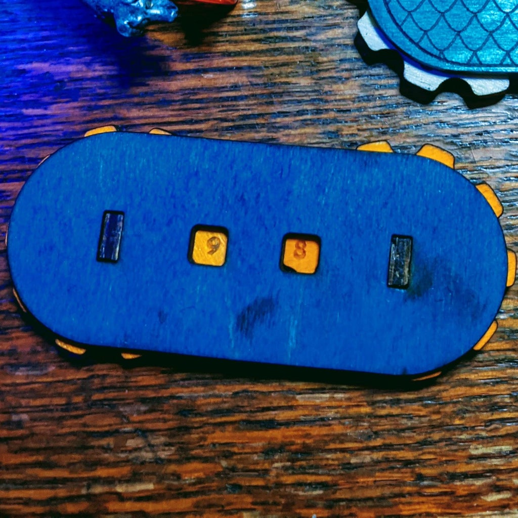
- *Confirm they are rotating the correct way and that the numbers are right side up.(they only rotate one way I chose to count down)*
- Place on the front cover making sure the direction of your scales matches the rear cover.
- Depending on your laser machines kerf and just how snug everything feels a drop of super glue can be added to hold the covers to the pegs.
With those steps done I had a really awesome hit point tracker. I can't wait to use at my next gaming session. Thank you all for taking the time to read this instructable. I hope you found it as entertaining to read as I did to write it. If you make your own tracker please post a picture or just drop a comment here I'd love to hear your thoughts. If you want to see project photos before they hit instructables or want to see the projects that don't end up on instructables you can find me on instagram. Thanks again.

Runner Up in the
Role Playing Game Challenge


