

Introduction: How to Solder Pins Header


How to solder pins header on Arduino Micro or any other kind of PCB.
Step by step tutorial, with no steps to skip by Awesome PCB.
As it is known, we can buy two type of Arduino boards, with header pins soldered on it ready to go, and second version without header pins. When we bought version without pins then we need to solder them.
The main target of this instructable is to show how to do this.
Step1 - What do we need?
Step 2 - Fixing PCB
Step 3 - Preparing for soldering
Step 4 – Rosin
Step 5 - Soldering of the pins header
Step 6 - Checking results with Arduino IDE
Step 7 - Additional tips - how to save space on bread board with ArduShield and get immediate access for pins Arduino UNO, Nano, Mini, Micro, Pro Mini and other derivative boards.
You can download PDF directly from here.
Step 1: What Do We Need?

1. Arduino Micro or any other board
2. 2 strip of THT pins - 17 pins each.
3. Bread board - this is not a must. It only give you better control over
soldering process and keep everything stable.
4. Tin
5. Resin - to keep clean solder place from contamination.
6. Soldering station - to melt tin and solder SMD on the PCB.
7. Arduino IDE
8. Resistor from range 220R to 510R
9. LED to check result if everything is working fine
10. Connecting cable for bread board
11. USB cable
12. ArduShield
Step 2: Fixing PCB


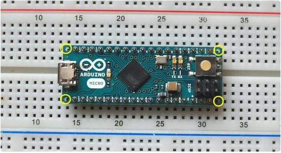
Mount THT pins on bread board.
Raster betwean 2 rows of pins in case of Arduino Micro is 0.6inch. Raster of the hole on the Arduino Micro allowed you to place standard connector with pith 0.1inch (2.54mm).
Each strip have to have 17 pins.
Make sure that holes marked on yellow colour should stay empty. They are not connected electrically with board. Place connector symmetrically.
Step 3: Preparing for Soldering

Turn on the soldering iron and after the warm-up, soak the tip for 2-3 seconds in the rosin to clean it of impurities.
Step 4: Rosin

If you are using a soldering iron transformer, leave a drop of rosin on the top of the tip.
This will facilitate soldering tin to pad and THT pin on the PCB in the next step.
Step 5: Tin - Soldering of the Pins Header


Stick tin and dart to the pin and turn on soldering station.
After 2-3 second tin will start melt and connect to THT pin and pad on the PCB.
Solder in that way all of the pins step by step.
Step 6: Checking Results With Arduino IDE


Now it's time to see if the pins are properly soldered. Verification will be done using the Arduino IDE environment USB cable, LED and resistor.
Connect one led of the resistor to GND, second leg of resistor connect to shorter leg of the LED (Catode). Longer leg of the LED (Anode) connect to first pin of the cable. Second pin of the cable connect to tested pin.
Open Arduino IDE.
Connect Arduino Micro via USB cable to PC.
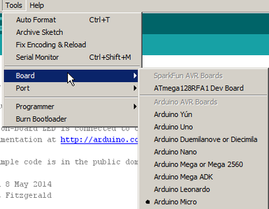
Select from top menu Tools proper board, in our case Arduino Micro.
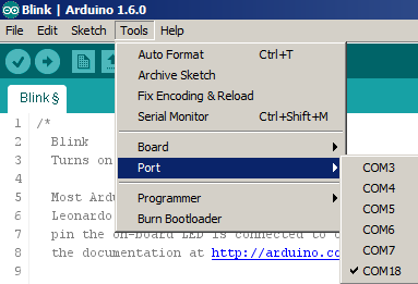
Select from top menu Tools proper serial port.
Copy to empty sketch below code.
/*LED checking
 This program is indended for check if pins are soldered properly on your Arduino board.
 If you have purchased a Arduino that does not have soldered pins,
 this program will allow you to check that the pins are properly soldered to the PCB.

Check detailed documentation how to soldered properly THT pins and check the
result can be found at   <a href="http://www.AwesomePCB.com" target="_blank">http://www.AwesomePCB.com</a> This  example code is in the public domain.

modified 06 January 2016
by Awesome PCB


*/ the setup function runs once when you press reset or power the board
void setup() {


  // initialize digital and analog pins as an output.
  pinMode(0, OUTPUT);
  pinMode(1, OUTPUT);
  pinMode(2, OUTPUT);
  pinMode(3, OUTPUT);
  pinMode(4, OUTPUT);
  pinMode(5, OUTPUT);
  pinMode(6, OUTPUT);
  pinMode(7, OUTPUT);
  pinMode(8, OUTPUT);
  pinMode(9, OUTPUT);
  pinMode(10, OUTPUT);
  pinMode(11, OUTPUT);
  pinMode(12, OUTPUT);
  pinMode(13, OUTPUT);
  pinMode(A0, OUTPUT);
  pinMode(A1, OUTPUT);
  pinMode(A2, OUTPUT);
  pinMode(A3, OUTPUT);
  pinMode(A4, OUTPUT);
  pinMode(A5, OUTPUT);
  pinMode(A6, OUTPUT);
  pinMode(A7, OUTPUT);
}


// the loop function runs over and over again forever
void loop() {


  // turn the LED on (HIGH is the voltage level)
  digitalWrite(0, HIGH);
  digitalWrite(1, HIGH);
  digitalWrite(2, HIGH);
  digitalWrite(3, HIGH);
  digitalWrite(4, HIGH);
  digitalWrite(5, HIGH);
  digitalWrite(6, HIGH);
  digitalWrite(7, HIGH);
  digitalWrite(8, HIGH);
  digitalWrite(9, HIGH);
  digitalWrite(10, HIGH);
  digitalWrite(11, HIGH);
  digitalWrite(12, HIGH);
  digitalWrite(13, HIGH);
  digitalWrite(A0, HIGH);
  digitalWrite(A1, HIGH);
  digitalWrite(A2, HIGH);
  digitalWrite(A3, HIGH);
  digitalWrite(A4, HIGH);
  digitalWrite(A5, HIGH);
  digitalWrite(A6, HIGH);
  digitalWrite(A7, HIGH);
}
//END of code____________________________________________________________
Copy to empty sketch below code.
Save the sketch (CTRL + SHIFT + S).
Reload the sketch (CTRL + R).
Up load to (CTRL + U).
After successfully uploading a program to Arduino Micro level of each digital and analog pin shoud have HIGH state.
Now go with nod of cable by each pin. If pin is soldered properly LED will be turn on.
Step 7: Additional Tips Hot to Improve Your Experience With Arduino and ArduShield


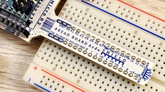


ArduShield it is most versatile development shield for most popular Arduino boards like a Arduino UNO R3, Mini, Pro Mini V5, Nano V3, MicroR3, Leonardo, Yun, Zero, Galileo Gen2 and many other derivative boards created by great community of people.
Tip 1.
How to save space on bread board with ArduShield and get immediate access for pins Arduino UNO, Nano, Mini, Micro, Pro Mini and other derivative boards.
Tip 2.
Use Arduino Micro and other Arduino with other shields
Tip 3.
Move Arduino pins and power supply to bread board
Tip 4.
Develope two prototype on one bread board with ArduShield
Check rest of the great feature about ArduShieldhere.

Participated in the
Arduino All The Things! Contest


