

Introduction: How to Use Blender 2.71: Basics


Hello, everybody!
Many of you have heard of or are familiar with 3D printing, and perhaps some of you are fortunate enough to have access to a 3D printer. Normally, when people want to 3D print a part, they find a pre-made 3D model on places like Thingiverse, Repables, YouMagine, or GitHub.
While this is useful, I would personally rather design my own part for my own satisfaction and sense of accomplishment. Originally, I hoped that I could use MakerWare for the Replicator 2 MakerBot that we have here at Digilent to design things, but I rapidly found out that this was simply not possible.
So, this meant that I needed some form of 3D modeling software. MakerBot has a nice list of various 3D modeling software that exist out there and I happened to pick Blender since it appeared to be pretty robust in it's capabilities and since I had a small amount of previous experience doing completely unrelated 3D modeling, I figured I could get the hang of it eventually.
Step 1: What to Expect
While this did happen to be true (hence this Instructable), learning how to use Blender the first time took longer than I expected and was (and still is) a little frustrating at times.
Nevertheless, I still think it is a great 3D modeling software and hope to alleviate some of the frustration by showing you today some of the basics (i.e. the stuff that I know how to do) on designing your own 3D model. Keep in mind that this is scratching the surface so-to-speak and that there are many other things that Blender is capable of such as texture, lighting, animation, and physics. You can download Blender for your appropriate system here.
A lot of what I learned on how to use Blender came from the extensive application-specific tutorials done by Neil Hirsig for his Blender 3D Design Course. His particular version of Blender (2.6x) is older than the one I am using (2.71), but I have not seen any major differences (at least not yet). The wiki for Blender (also for 2.6x, but works for 2.7x) is also a good resource although, like most wikis, it does not do the nice step-by-step examples.
For those of you that are interested, I will be covering the following topics:
- So... what buttons/tabs should I concerned about?
- Moving the screen
- Adding and naming objects
- Moving Objects (parts 1, 2, and 3)
- Object and Edit Mode
- Manipulating Objects
- Sizing and Scaling
- Specific Sizing
- Extruding
- Slicing
- Bisect
- Knife
- Knife Project (parts 1 and 2)
- Adding and Removing Features
- Joining and Separating
- Subdividing
- Subdivide
- Loop Cut and Slide
- Everything else
Step 2: So...what Buttons/tabs/keys Should I Be Concerned About?

We will go over all of the buttons/tabs/keys that I have (personally) found to be relevant, but I imagine there are many more shortcuts or other ways to do things. Please feel free to comment if I'm missing something that you would be a good thing to add to this particular tutorial and I'll work it in.
But back to our opening screen. Naturally, this picture doesn't show any keyboard shortcuts (here's a small list) or the mouse, but I'll get to those on a more appropriate step. There are several different tabs up on the main screen that we will be using fairly often.
At the top we have the traditional file header where we can save and open our various .blender files.
In the upper-left there is the Tool Shelf where you are able access various actions like moving the object, slicing, creating new objects, and other complex features like animation. I personally don't use this toolbar much except for slicing (which you'll only be able to see when in edit mode; more on that soon).
In the upper right there is the Outliner Editor which is a nice way to see all of the objects that you have and rename them if you so desire. You can also change their accessibility here such as if they are visible on the screen, if you can click on them and subsequently edit them, and if you can render them (an animation thing, I believe).
Below the Outliner is the Properties Editor where you can decide what units you are working in, change the object orientation, the texture of objects, add modifiers to objects, along with a variety of other features.
Finally at the bottom there is the 3D View Editor where you can add more objects, change between Object, Edit and other modes, change your coordinate system, how the objects are viewed such as solid or mesh forms, and what layer you are on. A layer is kinda like a new tab so that you can be working on multiple objects but not have them competing for space on the viewport.
There are many other tabs that you can see and choose from, but these particular five will be the ones that we'll end up using.
Step 3: Moving the Screen


Being able to maneuver your point of view is arguably one of the most important things to be able to do in order to generate a 3D model. Within Blender there are several different ways to do change your point of view.
In the 3D View Editor (on the bottom left), when you click on the "View" button, a list of options will appear offering various points of view along with their corresponding hotkeys. These are helpful if you want to orient or slice an object on a specific side and need a precise orientation.
I recommend putting the view into Orthogonal Perspective by keypad number 5. This helps make sure that the sides are not visually skewed like they are in the User Perspective, if that is a concern to you. Pressing keypad number 5 will toggle between the two viewpoints.
Keypad numbers 4 and 6 will rotate the screen left and right, respectively, and numbers 2 and 8 will rotate the screen down and up, respectively. 0 will toggle the Camera Perspective on and off, but I don't think number 9 does anything.
While a few of these are nice, especially for getting in a precise point of view, I personally prefer to use the mouse to do the vast majority of the screen rotation. The scroll wheel adjusts the zoom level and when combined with the SHIFT key, it moves the screen up and down. When combined with just the CONTROL key (or COMMAND key for Mac's presumably), the screen moves left and right. Pressing both the SHIFT and CONTROL keys at the same time and scrolling adjusts the rotation of the screen.
The middle mouse button allows you to freely drag your orientation around, and when combined with SHIFT freely drags the screen while keeping the same distance. The middle mouse button with CONTROL allows you to freely zoom in and out, which isn't very helpful since scrolling already does this.
Step 4: Adding and Naming Objects


Let's add another object to our viewport. We can do this by left clicking where on the screen where we want our object to appear and then clicking on "Add" tab on the 3D View Editor at the bottom and then selecting a type of object. You may also add objects by holding SHIFT and pressing the "A" key, or by going to the "Create" tab on the Tool Shelf on the left. For the purpose of this Instructable, I will select a mesh UV Sphere.
Once the UV Sphere has been initially placed, we can make some initial adjustments to the sphere under Add UV Sphere on the left (you may have to drag up the menu to see all of it). Here we can adjust the number of faces, rings, size, rotation, and location for this particular object by either entering in a number in the selection bar, by clicking the left and right arrow keys, or by clicking and holding the left mouse button on the selection bar to drag an invisible bar back and forth.
We can then name our object by looking in the upper right at the Outliner Editor for the object name in white letters and either double left-click or right click to change its name, along with the other features mentioned in step 2.
Step 5: Moving the Objects- Part 1


We can also move objects around to wherever we want them to go. Right now the default object, a cube, is outlined in yellow to indicate that it is selected. For the sake of mentioning it, we can deselect our object by pressing the "A" key. Pressing the "A" key again will select all of the objects that are currently on our viewport including the cube, the lamp, and the camera. To select an object by itself, right mouse click on it.
The normal left mouse click will move the "hair trigger" cursor around the screen, but this does not really affect anything on the screen.
Objects themselves can be moved in several different ways. The Translate button in the Tool Shelf will make the selected object bounded in white which will then allow it to be moved freely in the view port with your mouse. To place the object, click the left mouse button. A selected object can also be freely moved by pressing the "G" button or by pressing and holding the right mouse button.
Step 6: Moving the Objects- Part 2

It's difficult to place an object in the desired location in free translation, but you are able gain some more control by pressing the "X", "Y", or "Z" keys to have the object move in a specific direction. Pressing the keys repeatedly will toggle between local, global, and free movement. Alternatively, you can move the object initially in a specific direction by clicking on one of the red, green, or blue arrows. Again, to place an object use the left mouse click.
I know from personal experience that it's hard to get an object moved to a precise location, but within Blender, after you move and place an object somewhere, a menu on the left will appear which will allow you to specify how far the object should be moved. Remember that you can change your screen position by various keypad numbers as well as the middle mouse button to check if the object is where you want it to be.
Similarly, you can rotate an object by right-clicking on it to select it, and then pressing the "R" key along with the "X", "Y", or "Z" keys to specify a rotation direction.
If you happen to be moving the wrong object, you can right click to return the object to its original location. Alternatively, if you have already placed the wrong object, you can press the "CRTL" and "Z" keys to undo the last action.
Step 7: Moving the Objects- Part 3


You'll notice that once you initially move a new object, you'll no longer have the menu on the left to change the number of faces, rings, or other similar options. Unfortunately, I do not personally know of a way to change those sort of options within Blender without creating a brand new object. Granted, it is possible to subdivide the object into more faces (more on that later), but that isn't quite the same.
However, you may specify an objects location, rotation, and scale after initially placing it. This can be done by selecting the Object option in the properties editor on the right hand side of the screen. Here, you are free to change where the object is located and oriented in the viewport, as well as the scale for each direction.
Step 8: Object and Edit Mode


Before we get too much further (and because we'll need this feature to do almost everything else anyway), we'll talk about the differences between two of the main modes that Blender has available: Object and Edit Mode.
So far, we have been working in Object Mode where we are able to manipulate objects on more of a global scale. On the other hand, Edit Mode is where a lot of detailed work can be done.
There are two ways to change what mode Blender is operating in. You may select the pop-up menu on "Object Mode" in the 3D View Editor at the bottom to choose a new mode, such as Edit Mode. The faster way, which I use, is the TAB button on your keyboard which toggles between Object and Edit Mode for you.
On the main screen of Edit Mode, you can see that the object that was previously selected in Object Mode is now divided up into individual parts: vertices, edges, and faces. You can select any one of these by choosing the appropriate selection type in the 3D View Editor at the bottom and then right-clicking on the appropriate feature. Holding down shift while right clicking will allow you select multiple of the same feature. Again, you may press the "A" key to select/deselect all of a features of the selected objects.
On the left hand side of the screen, the Tool Shelf has changed its options to allow for extrusions and various forms of slicing (more on that later) under the "Tools" tab, as well as shading options under the "Shading/UVs" tab.
Step 9: Manipulating Objects: Sizing and Scaling

Finally! We are now at the heart and soul of 3D modeling: manipulating the objects to look like what we want them to.
You likely noticed the scaling option that was available when we initially placed an object and in the Object tab in the Properties Editor. Both of these work pretty nicely, but if you are designing a 3D model that you want to be on a real life scale, such as the metric scale or imperial scale, we'll need to change our units to these as opposed to using the "Blender Unit" scale.
To change what units we are operating with, click on the "Scene" tab in the Properties Editor. In this tab, there is a "Units" option where we can select none (for no pre-defined units), Metric, or Imperial units. The standard metric unit is the meter and the standard imperial unit is a foot.
The scaling option is there for you to change the size ratio of your object compared to the standard unit size. For example, in metric units, the default cube is 2 meters wide, but when the scale is set to 0.1, the default cube is instead 0.2 meters, or 20 centimeters wide. Note that this scaling does not correlate with translating (moving) your object. At a metric scale of 0.1, if you told it to move "1" in the x-direction, the object will move 1 meter as opposed to 10 centimeters that the scale would supposedly suggest.
Step 10: Manipulating Objects: Specific Sizing

Having units are nice, but it is terribly frustrating to try to scale, extrude, and slice an object to the exact dimensions that you want it to be.
Luckily, there is something known as the Properties Panel display, which is toggled on and off by the "N" key. When you are in Object Mode, this panel can be used to specify exact dimensions of an invisible box around your part. The reason they use an invisible box is to simplify sizing non-"box" parts, such as a cone or a sphere, where we might have to give the dimension for every face that is on the sphere. Needless to say, I am very grateful, since that would be horrible otherwise.
This panel is also another way for you to specify the location and rotation of the selected object as well as a locking feature for that particular parameter from being accidentally changed, making the Properties panel my "go-to" for precise moving and sizing of objects.
Step 11: Manipulating Objects: Extruding


Extruding is a common 3D modeling feature where a feature, such as the side of an object, or set of features, such as a set of vertices, can be stretched/extended from their current position.
To extrude an object, go into Edit Mode and select the feature(s) that you want to extrude by right-clicking on them. Then, you may choose to extrude the whole region by clicking on "Extrude Region" in the Tools tab on the Tool Shelf or by pressing the "E" key. This should stretch out that particular region and can be set be left clicking or put back in the original position by right clicking. You may also extrude in a specific direction by pressing the "X", "Y", or "Z" keys.
You can also extrude individual faces (not other features) by clicking on "Extrude Individual" in the Tools tab on the Tool Shelf (no keyboard shortcut for this that I know of). If you have multiple features selected, it is easy to see that they are extruded in the direction orthogonal to the tangent plane; that is, they are extruded "directly away" from their original location.
Step 12: Manipulating Objects: Notes on Extruding


Note that in the post-extrusion picture where the top set of faces on the sphere was extruded downward through the sphere by toggling the appropriate coordinate direction, a hollow was left in the top of the sphere. This is because the objects that I am using are mesh objects, so they are hollow on the inside to begin with, so when a face of a sphere is extruded inward, an impression where the face was is left. The outside edges of the orginally selected faces were at the same time stretched to form walls on the inside of this impression.
In terms of 3D printing, the fact that the object is hollow is not an issue. The reason why is because the software that prepares a 3D model for the correct 3D printing format does not know what is on the inside of an object, just what the outside of an object is. That being said, you have to make sure that your model (if it is to be 3D printed) is "watertight". This implies that if you filled your hollow object with water, there isn't a hole somewhere on your object where the water could leak out.
Step 13: Manipulating Objects: Slicing - Bisect


Slicing is a very large part of manipulating objects to look as we, the user, want them to. Blender has several tools available to perform various slices.
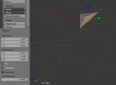
One such tool is called Bisect. This is a type of slice where you can create a slice (in Blender, this will be an edge) through selected features. To do this, select the desired faces or edges (in Edit Mode) and then click on the "Bisect" tool on the Tool Shelf.
Draw a line across the faces or edges to create a new edge on those selected features. This will also create an appropriately placed edge on selected features even if you cannot see them from your current perspective.
Once we have initially bisected our object, there are a few things that will be briefly available to us, much like the number of rings available to a newly created sphere. On the left side of the screen underneath the Tool Shelf there will be a Bisect menu. Here, you can adjust where your bisected line is located as well as a few other features. The "Clear Outer" and "Clear Inner" options are able to eliminate one side or the other of bisected edge and the "Fill" option will place a face connecting the bisected edges.
Step 14: Manipulating Objects: Slicing - Knife


Another slicing tool the Blender offers is the Knife tool. The main way that this particular tool differs from Bisect is through the way you select where the new edge is created. Rather than pre-selecting features and then drawing a line to cut through all of the features at once, you are able to select individual features as you go.
To use Knife feature, go into Edit Mode and under the Tools tab on the Tool Shelf on the left, select the Knife option. Your cursor will turn into a knife shape (not shown in the screen capture) and you can then select where to cut by left clicking with your mouse. The default setting is that your cursor will "snap" to edges and vertices when you get close to them, but you can change this feature along with other features through the hints at the bottom of the 3D viewport.
To confirm your chosen cuts, press the SPACEBAR on your keyboard. The only real rule with the Knife tool is that you cannot end a knife cut in the middle of a face on your object. The reason for this is because the Knife tool, like the Bisect and other slicing tools, create an edge. By the geometric nature of edges, you cannot really have a "hanging edge", so consequently you cannot end a knife cut in the middle of a face.
Step 15: Manipulating Objects: Slicing - Knife Project- Part 1


The last slicing option that I will cover in this tutorial is the "Knife Project" tool. This particular tool is the well known type of tool where you are able to cut out different shapes into the surface of objects.
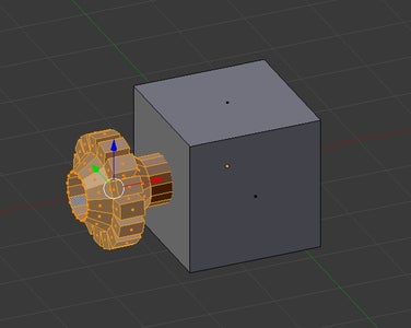
To use the Knife Project tool, you will first need two objects: the object that is to be cut and the object that is to be projected through the surface of that object. I happened to choose to create a star pattern by adding a circle mesh with 10 vertices and then using the "Push/Pull" option on the Tool Shelf in Edit Mode to pull every other vertex to create a star shape. In Blender, the object that is to be projected through, the "knife", has to be a flat object. Or at least I have not successfully used a Knife Project with a 3D object as the knife.
Then, while in Object Mode, select the object that is to be the "knife" with a right mouse click and then hold the SHIFT key and right click on the object that the "knife" is to be projected into. The first object, the knife, should be outlined in a orange-red color and the second object should have the yellow outline.
To actually do the Knife Project, press the TAB key to go back into Edit Mode; the "knife" should still be outlined in that orange-red color, the object that is to be cut may or may not be lit up depending if you have selected any features, but it does not matter if it is selected. On the Tool Shelf in the the Tools tab, press the "Knife Project" option. This will project the knife forward onto the surface of the object.
You may have noticed that the "forward" direction is entirely based on the current perspective in your view port. If you have the knife object exactly centered on the object to be cut and then rotate the camera, the resulting cut will be based on the camera angle, not the objects orientation to one another. Remember, you can use your Number keypad to jump to specific camera orientations.
Step 16: Manipulating Objects: Slicing - Knife Project- Part 2


There are two different visual results that can occur after using the Knife Project tool. The first is if your projection stayed within one face of the object that was being sliced, the shape will automatically be cut out of the surface with a couple of edges going from the edges of the face to the hole. These edges are fine since in 3D printing, or even just modeling, you will only see the outside of the object as you see it in Object Mode (with no awkward edges).
The second visual result is if your project spread across multiple faces. Here, edges of where the cut was made will appear and we can manually delete the object faces by selecting them and then pressing the "X" key and choosing "Faces".
You may also choose to cut all the way through an object in the Knife Project menu, just after you do the initial knife projection. To do this, select the "Cut Through" on the Knife Project menu which is below the Tool Shelf on the left.
Step 17: Manipulating Objects: Adding and Removing Features


After slicing an object, you may want to add some features, such as faces, to create walls for the hole that your Knife Project created in order to ensure that your object is watertight. Or perhaps you want to remove a particular feature so that it is not visually obtrusive. Blender is able to do both of these actions.
As for adding features, I am only aware of being able to add an edge or a face to an object. To do so, go into Edit Mode and choose vertex as your feature selection criteria. Then right click on the desired vertices (2 or more) and then press the "F" key to create a face connecting those points, or an edge if you only selected two points.
To remove features, we can select any type of features that we wish, but each one will imply different sorts of results. To actually remove the feature, select it and press the "X" key to bring up a menu of what you wish to remove. If a vertex is removed, each face and edge that was directly connected to that vertex will also be deleted.
If an edge is removed, the faces on either side of the edge will be removed, but the two vertices at the ends of the edge will remain presuming the edge was attached to other things. Removing a face will simply remove the face but keep the edges and vertices that were previously associated with that face.
Step 18: Manipulating Objects: Joining and Separating


Joining and separating objects are useful tricks in order to make sure that objects stay relatively fixed in relation to one another or lose their fixed relationship to one another, respectively.
To join two objects so that Blender treats them as one object (even if they are not physically touching each other), go into Object Mode and select one object by right clicking on it, and then hold down the "Shift" key and right click on all of the other desired objects. Then press the CONTROL key and the "J" key. All of the selected objects will get a yellow outline and will move, scale, and rotate together.
If you have two joined objects (or two parts of one object) that you wish to separate later on and the "Control Z" option to go back isn't viable, you can still separate them.
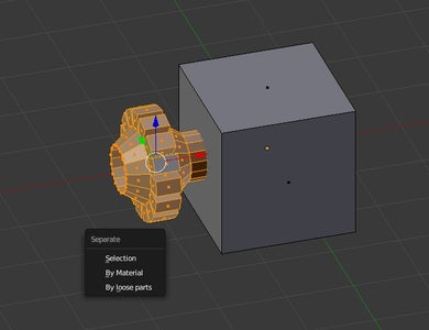
To separate objects, go into Edit Mode and select one set of features that you wish to separate. I know you're probably thinking this sounds like a daunting task, but luckily we have a nice keyboard shortcut. If you select one particular feature and then press the "L" key, Blender will then select all of the features related to that one feature and is smart enough to distinguish faces between two objects, even objects like a smaller cube joined to a larger cube.
To actually separate the objects, once you have the features you want selected, press the "P" key. This will bring up a small menu asking by what we want to separate by. I personally choose "Selection" since I have never changed the material type and I believe "Loose Parts" only works if they are not physically touching each other. The objects are now no longer associated with each other and there will be a new entry in the "Outliner Editor" in the upper right for the new object.
Step 19: Manipulating Objects: Subdividing- Subdivide

If you want to divide an object or a feature of an object into multiple parts, but don't want to be forced to try to use the Knife or Bisect tool to get equidistant divisions, there are a couple of tools available to get the job done; the Subdivide and Loop Cut and Slide tools. Both of these are available in Edit Mode in the Tool tab on the Tool Shelf.
The Subdivide tool takes the selected feature(s) and, not surprisingly, subdivides the selected features into equal sized parts, so an edge would be divided into two edges and a face would be divided into four smaller faces. After you have used the Subdivide tool, a menu will appear on the left where you may adjust the number of cuts along with some weird distortion and fractal features (which don't look like fractal like).
Step 20: Manipulating Objects: Subdividing- Loop Cut and Slide


Alternatively, to just divide your object along one direction, you can use the Loop Cut and Slide tool. This tool only works on a Blender determined set of particular features of an object (which again, Blender is smart about knowing which is which), so you cannot pick and choose individual features.
After clicking on Loop Cut and Slide, you are able to hover over your object to choose which set of features and orientation the Loop Cut should be and confirm the set of features by left clicking with your mouse.
You may then move your mouse to Slide the Loop Cut along that set of features and use the scroll wheel to adjust the number of cuts that are to be made. To help get your cut(s) at a precise location, at the bottom of the screen there is an Edge Slide value which tells you how far left or right you are from the center of the features. Left click once more to confirm the final cut.
It can be hard to Slide the Loop Cut into exact locations, so like most tools there is a menu that is available just after you complete (in this case) your Loop Cut and Slide to adjust the number of cuts, where the cuts are located, along with other features.
Step 21: And Everything Else
Thankfully, everything else (all of the other basics, texture, lighting, animation, and physics) is not going to be on this slide; I personally don't know how to do them or know that it would rapidly deviate from the "basics" that I was originally intending to show in this Instructable, and goes beyond the scope of the work that I would do here at Digilent.
If you have any questions or comments, please feel free to comment and I will get back to you as soon as I have an opportunity. If you know of something else that Blender can do, or another useful keyboard shortcut that falls within the scope of this Instructable, please let me know and I'll do my best to work it into the tutorial.
To find out what I and the rest of the Digilent team is up to, check out the Digilent Blog as well as the Digilent MakerSpace!


